NICE Robus Hi-Speed RB500 HS – high-speed drive for sliding gates (A)
| Product availability: | replaced | This product is no longer manufactured, but fortunately it has been replaced by a newer model. |
|---|


Description of NICE Robus Hi-Speed RB500 HS – high-speed drive for sliding gates (A)
Available replacement!
The fast drive for NICE Robus Hi-Speed RB500 HS sliding gates has been replaced by a newer model NICE Robus Hi-Speed RBS600 HS.
The NICE Robus Hi-Speed RB500 HS gate opener is designed for fast operation of sliding gates up to 500 kg and a clear opening width of up to 7 m. It has an electromechanical stop switch. The gate opener is non-reversible.
The standalone NICE Robus Hi-Speed RB500 HS sliding gate opener (our code NICE-RB500HS-A) includes:
- an electromechanical NICE Robus Hi-Speed RB500 HS gate opener with a capacity of 500 kg and a maximum gate leaf length of 7 m, with an integrated control unit RBA3/HS without a radio receiver (OXI).
- 2 × release keys for manual operation of the gate opener (required in the event of a power failure)
- gate-opener installation components, anchor fasteners and bracket, and gate-opener limit-switch stops
The gate opener is compact, safe and practical, making it ideal for both residential and commercial use. Impact-resistant cover, aluminium-alloy body with an epoxy coating.
The gate opener is suitable for automating sliding gates weighing up to 500 kg, with a gate leaf length of up to 7 m. These values apply under the conditions specified by the manufacturer, including weather conditions, temperature variations, gate rigidity and, above all, smooth gate movement. These conditions cannot always be achieved or controlled, so we recommend using the NICE Robus RB500 gate opener for gates operating at 80% of these limits. See the Gate Opener Selection chapter for more information.
A very user- friendly technology BlueBUS allows up to 7 pairs of photocells to be powered and controlled using a two-core cable.
Temperature sensor adjusts the gate opener's pulling force according to the weather conditions. The gate opener also includes a thermal fuse.
The gate opener's speed, force and automatic-closing pause time are adjustable, along with many other settings; see Programming.
Diagnostics using warning beacon.
The gear module 4 is compatible with the rack available in our range.
Robus 500HS gate opener functions “Slave unit” ensures automatic synchronisation of two motors. This means that two sliding gates moving towards each other can be automated.
The NICE Robus RB500HS gate opener is an electromechanical model suited to the climate in Slovakia and complies with all European safety standards.
Accessories compatible with the NICE Robus RB500HS gate opener
We also recommend purchasing compatible optional accessories for the gate opener, or choosing one of our already pre-assembled value kits:
| What | Why | Type |
|---|---|---|
| Beacon | The beacon flashes to indicate gate movement—ideal for exits with poor visibility. It also has a built-in antenna for greater remote-control range. | |
| Photocells | They detect obstacles while the gate is closing and stop its movement, preventing the gate from hitting a car or anyone. | |
| Transmitter |
For remote control of the gate. |
- Era One (ON2E, ON4E) |
| Receiver | Required for remote control of the gate. | - OXI - SMXI |
| Antenna | For increased remote-control range. | - built into the beacon LUCYB, MLBT - ABFKIT antenna only |
| Keypad | If you forget your remote control, if many vehicles or people visit your premises, or if you do not want to give everyone a remote or open the gate yourself. | - MOTXR |
| Rack | Required to automate the gate opener—the opener cannot move the gate without a rack. | - nylon LZ-1 with a steel reinforcement - steel LZ-2 - stainless steel LZ-7 |
Manuals and documents for download
NICE Robus RB500-HS operator limits
These values are those recommended by NICE. Based on our experience, we recommend allowing the operator a reserve of approximately 80% of the stated values:
| Maximum | Recommended | |
|---|---|---|
| Gate leaf length | 7 m | 5 m |
| Gate leaf weight | 500 kg | 400 kg |
Using the operator at maximum capacity reduces its service life — see the estimated operator service-life calculation based on stress factors:
NICE Robus RB500-HS operator service life
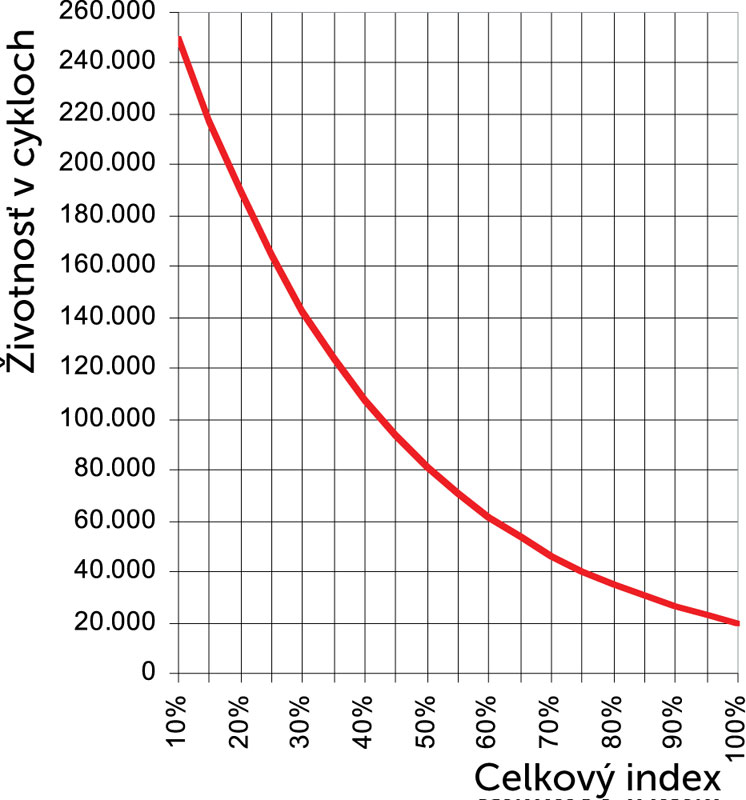
In the table below, add the stress indices for the gate leaf weight and length, then add the indices for any other applicable factors. Then use the graph to find the operator's service life, expressed as the number of cycles.
Example: I have a gate with a clear opening of 4.5 m and a structure weighing up to 200 kg, including infill (a standard gate). I calculate the gate leaf length index as approximately 15, plus a gate weight index of 10. To be on the safe side, I also add an index of 10 for low temperatures, since our winters are harsher, giving a total index of 35. The graph shows an operator service life of approximately 120,000 cycles. At 10 operating cycles per day, this gives an estimated service life of approximately 32 years.
| Overall automation characteristics | Index | Service-life graph |
|---|---|---|
| Gate leaf weight |
The recommended maximum total index is up to 75%. (i.e. 40,000 cycles, which corresponds to 10 years at a typical rate of 10 cycles/day)
|
|
| Up to 200 kg | 30 | |
| 200–400 kg | 40 | |
| Gate leaf length | ||
| Up to 4 m | 15 | |
| 4–6 m | 25 | |
| 6–7 m | 35 | |
| Other factors (if the probability of occurrence is greater than 10%) | ||
| Ambient temperature above 40°C or below 0°C, or humidity above 80% | 10 | |
| Dusty environment | 15 | |
| Saline environment | 20 | |
| Photocell activation | 20 | |
| STOP input activation | 30 | |
| Speed above "L4 - Fast" | 25 | |
| Peak function enabled | 25 | |
Installing the NICE Robus RB500HS operator
The installation method for the operator is different for a track-mounted sliding gate and a cantilever sliding gate different. For a track-mounted gate, the operator is generally installed at ground level, while for a cantilever gate, it must be operators raised using, for example, threaded rods (Ø8 threaded rod), a custom-made bracket, a concrete plinth, etc. The key factor is the height of the toothed rack, which should ideally mesh with the operator's drive gear; see The toothed rack and its end stop.
Wiring
A typical (optional) operator and accessory wiring layout looks like this:
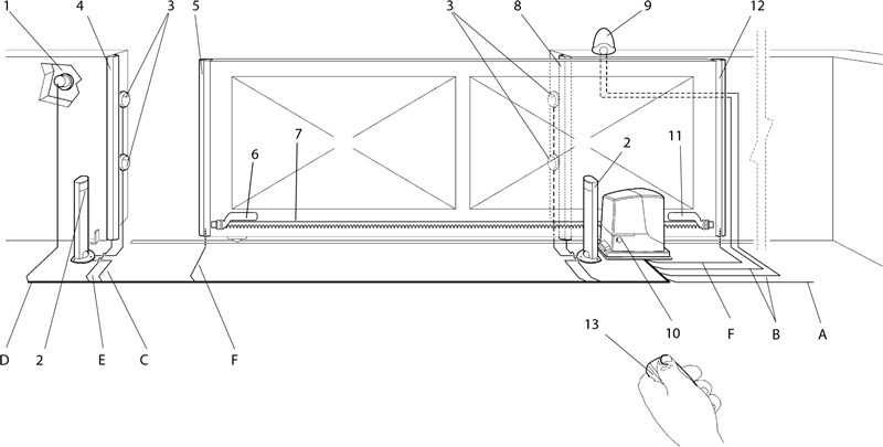
Accessories list
|
|
Wiring list
| Purpose | Type | Max. length |
|---|---|---|
| A. Power supply | 3×1.5 mm2 | 30m, for longer lengths 3×2.5mm2 + grounding |
| B. Flashing light with antenna |
2×0,5mm2 |
20 m 20 m (recommended: less than 5 m) |
| C. Photocells | 2×0,5mm2 | 30 m, over 30 m: 2×1 mm2 |
| D. Key switch | 4×0,5mm2 | 50m (or 2 pcs. 2×0,5mm2) |
| E. Static safety edges | 2×0,5mm2 | 30m |
| F. Moving safety edges | 2×0,5mm2 | 30m |
Installation
See "At what height should I install the operator".
Rack and its end stop
The gate moves by transferring the torque of the operator's pinion into linear motion via the rack-and-pinion drive on the operator's rack. There are two commonly used types of racks:
 |
Nylon rack (optionally with steel reinforcement) – attached to the gate with self-tapping screws through the mounting holes. Ideal for relatively light and short gates. Movement is quiet thanks to the friction between the steel pinion and nylon rack. |
 |
Steel rack – attached to the gate by welding on threaded brackets, to which the rack is then screwed. Used for longer and heavier gates. Movement is slightly noisier due to friction between the steel pinion and steel rack. |
It is essential that the operator pinion module is compatible with the rack module. The operator NICE Robus RB500HS has a pinion module of 4.
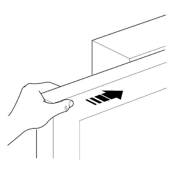
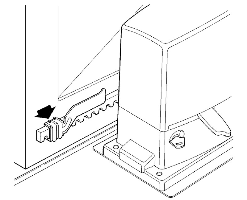
The operator detects the end position during opening and closing using limit stops fitted to the rack:
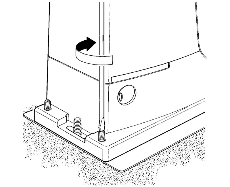
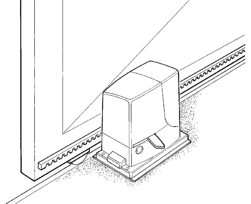
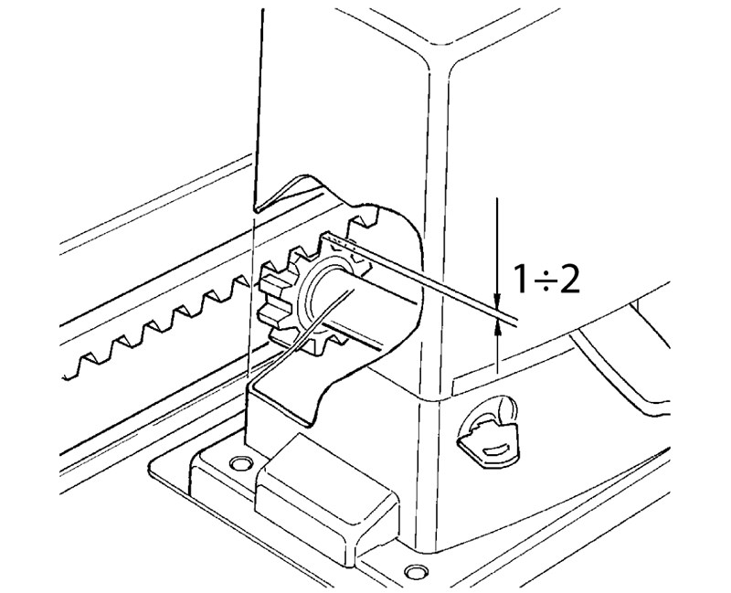
| 1. Level the operator using the four adjustment points | 2. The gate and operator must be level | 3. Leave a gap of approximately 1-2 mm between the rack and the operator pinion so that the gate's weight is not transferred to the operator. |
 |
 |
 |
| 4. Tighten the operator's mounting bolts so it does not move under load | 5. Move the gate to the open/closed position and install the limit stops so they activate the operator's limit switch at the end position. | |
 |
 |
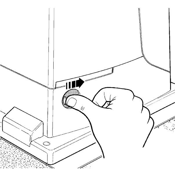
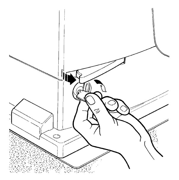
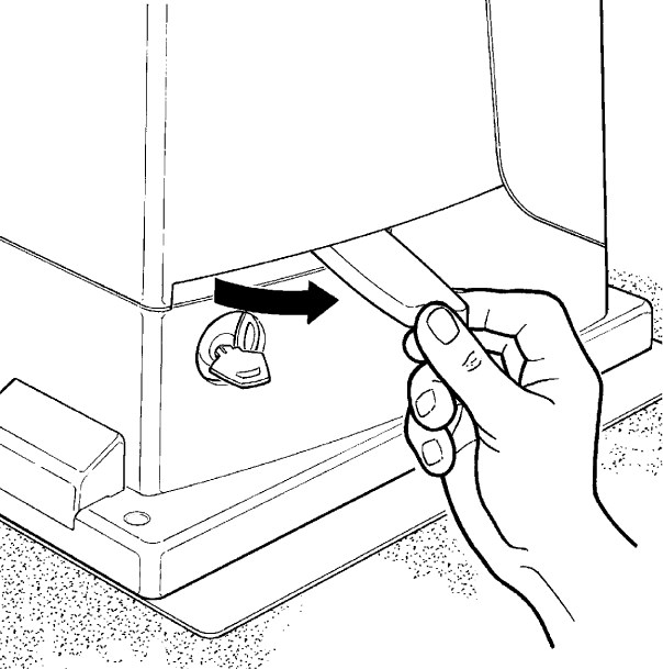
Manual release of the NICE Robus RB500HS operator
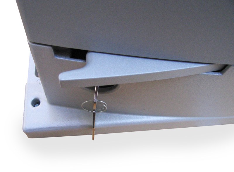 |
In the event of a power failure, you will not be able to operate the gate using a remote control. Therefore, the operator can be released using the release key and the gate can be moved manually: |
| 1. Slide open the release lock cover | 2. Insert the release key and turn it clockwise |
|---|---|
 |
 |
| 3. Pull out the release lever | 4. You can move the gate manually |
 |
|
How can I order this item?
Choose the option that suits you:
- order online: use the buy button to add the goods to your shopping cart (you will find the buy button here in the product variants table).
- order by email: place your order at [email protected]