Common situations encountered when building a sliding gate
DIY cantilever sliding gate
Dear customers, we appreciate the trust you place in us with your purchases. Our store was established to recommend and supply the right products for building a sliding gate, so we have prepared these guides for you and continue to update them based on your feedback.
Page contents
1. Choosing components for a cantilever gate
- Universal component kits
- Choosing a C-profile
- Choosing support carriages
- »» Anchoring carriages to a concrete foundation
- »» Concrete foundation dimensions
- Choosing gate guides
- Choosing a gate operator
»» NICE operator manuals - Cantilever gate construction
- Telescopic cantilever gate
2. Frequently asked questions and answers:
1. Can a cantilever gate be built on a slope?
2. Do the carriages or the inside of the C-profile need to be lubricated to ensure the gate runs smoothly?
3. Why choose a cantilever gate? What are the benefits?
4. Why do you recommend adjustable, tilting carriages? What are they used for?
5. Which components do customers most often buy in addition to the KIT?
6. What ground clearance does a cantilever gate have?
7. Where should the toothed rack be attached to the gate?
8. At what height should the NICE operator be installed?
9. What size of square hollow section should be used to build the cantilever gate?
10. What cables should be used to power the NICE operator?
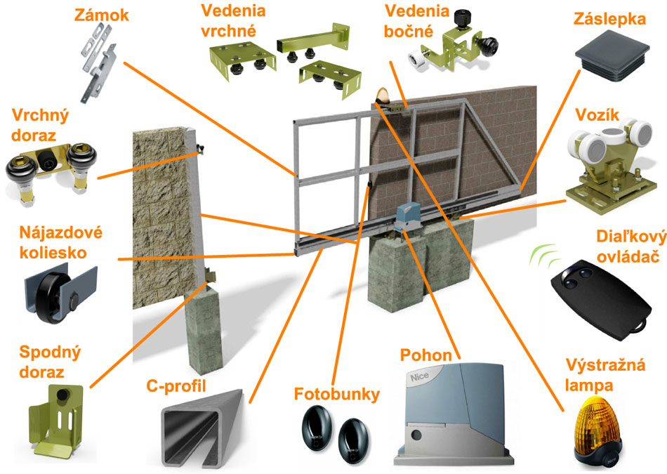
3. Description of the main components of a cantilever gate
| Carriage with bearing rollers | Closing pocket | Electromechanical operator |
| C-profile | Top/side guide | Remote control |
| Bottom catcher | Profile end cap | Photocells |
Choosing components for a cantilever gate
Universal component kits
To make choosing easier for you, we have put together COMPONENT KITS for cantilever gates.
We can customize the contents of the KIT on request. If you have a specific request or would like advice, write to [email protected].
Note: the clear opening is the distance between the posts that remains unobstructed when the gate is open.
Choosing a C-profile
Choose the C-profile based on the gate leaf's total weight and length, the clear opening width, frame construction, infill type, and wind load. The following limits are a general guide:
- for gates weighing up to 400 kg with a clear opening of up to 4.5 m: C-profile 70x70x4 mm
- for gates weighing over 400 kg with a clear opening wider than 4.5 m: C-profile 80x80x5 mm
These values are indicative only. If only one limit is exceeded—for example, if the gate weighs less than 400 kg but the clear opening is wider than 4.5 m—the choice should be checked against the complete design. The overall load capacity is also affected by the reinforcing profile above the C-profile, the rest of the frame material, the infill, and local wind conditions.
Example:
Standard dimensions of a cantilever gate with a clear opening width of 400 cm and a height of 150 cm, using a 70 × 70 × 4 mm C-profile, an 80 × 40 × 2 mm reinforcing profile, and all other structural steel gate components made from 60 × 40 × 2 mm material, the following values apply:
| Gate weight (without visible infill): | approx. 120 kg |
| Load per 1 m: | 0.9 kN/m (90kg/1m) |
| Compression/tension reactions: | 18.49 kN / 10.81 kN |
| Total load capacity: | 480 kg |
For the example above, a 70 × 70 × 4 mm C-profile and matching carriages with five bearing rollers, i.e. the components from kit SADA-01 or SADA-03-RBS. The frame itself weighs approximately 120 kg; the remaining capacity for the infill is indicative and should be checked against the specific design before fabrication.
Contact us: we’ll check your gate specifications and recommend suitable components. Email: [email protected].
Complete range of C-profiles
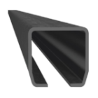 Black C-profiles |
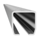 Galvanized C-profiles |
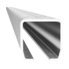 Stainless steel C-profiles |
All C-profile sizes and finishes »
Choosing support carriages
- for a gate with a passage width of up to 2.8 m: carriage with 3 bearing rollers
- for a gate with a passage width of up to 4.5 m: carriage with 5 bearing rollers
- for a gate with a passage width of up to 6.5 m: carriage with 8 bearing rollers
Most common carriage types
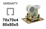 Carriage with 3 rollers |
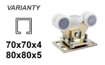 Carriage with 5 rollers |
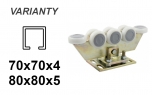 Carriage with 8 rollers |
All types of sliding gate carriages »
This guide is indicative and applies to typical gates. Carriage suitability should be assessed in conjunction with the gate’s weight, overall leaf length, infill type and wind load. If you’re unsure which to choose, contact us.
Anchoring support carriages to a concrete foundation
Support carriages can be:
- fixed to threaded rods cast directly into the foundation
- fixed to threaded rods in an already cured concrete foundation using a chemical anchor
- fixed with steel anchors in an already cured concrete foundation
For detailed information about anchoring a sliding gate find out HERE. We’ll also be happy to advise you on the dimensions of the concrete foundation.
Concrete foundation dimensions for a cantilever gate
Detailed concrete foundation dimensions for cantilever gates of various sizes can be found HERE: concrete foundation dimensions.
Please note:
- the foundation must extend below the frost line, as determined by local conditions; the required depth may vary from one area to another,
- before pouring the concrete, remember to provide a power supply and cable runs for the drive. Even if you’re planning a manually operated gate, it’s a good idea to install conduit in advance. You can then drive install it at any time in the future.
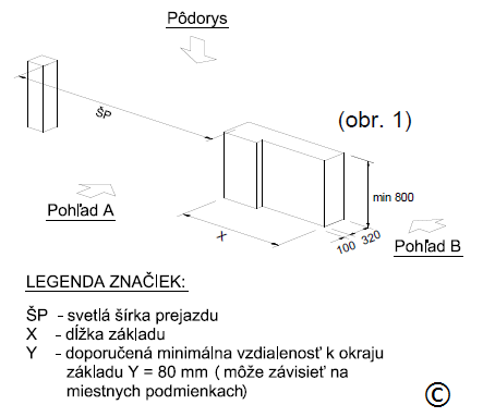
For a description of dimension “X” and further details, see HERE: concrete foundation dimensions.
Choosing the gate guide
Top guide is suitable if the gate infill does not extend above its frame. It is fixed to an existing fence or a separate levelling post. Side guide is suitable when the infill is to extend above the gate frame; the guide rollers are mounted on the post on the inside and run in a U- or L-profile on the gate leaf.
The choice of guide depends on the space around the gate, the available anchoring options and whether the infill should extend above the frame’s top profile. If so, a side guide is generally more suitable. Individual guide rollers can be used with a custom-made guide.
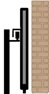 Side guide |
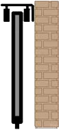 Top guide |
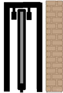 Individual rollers |
Complete range of sliding gate guides »
Example of use side guide (BR-43G):
You can use an L-profile or U-profile for the side guide to run in. Ideally, use two of these guides side by side: one “pushes” the gate outwards and the other “pushes” it inwards, keeping the gate properly centred.
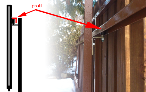
Recommended top guide (VVR-3-G):
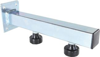
For typical applications, we recommend the universal top guide VVR-3-G with a length of approximately 25 cm. The roller position and clearance between the gate and fence can be adjusted to suit the installation. If you need a wider adjustment range, an extended VVR-3-G-300 guide with an overall length of 30 cm.
Choosing a gate operator
When choosing a gate operator, consider not only the gate’s weight, but also the leaf length, frequency of use, required speed, and wind load. For typical use, here are some current NICE models:
- for gates up to 400 kg: NICE RBS400,
- for gates up to 600 kg: NICE RBS600,
- for gates up to 1000 kg: NICE RB1000.
Current NICE operators and manuals
| Gate weight up to | Current operator | Documentation |
|---|---|---|
| 400 kg | NICE RBS400 | Official NICE documentation |
| 600 kg | NICE RBS600 | Official NICE documentation |
| 1000 kg | NICE RB1000 | Official NICE documentation |
Estimating gate weight
For example, a standard cantilever gate measuring 400 × 150 cm, with a 70 × 70 × 4 mm C-profile, whose frame is welded from 60 × 40 × 2 mm box section weighs approximately 125 kg. The table also shows weights for other opening widths, using the same box-section material (S235JRH structural steel, size 60 × 40 × 2 mm):
| 300x150cm gate | approx. 90 kg |
| 350x150cm gate | approx. 110 kg |
| 400 × 150 cm gate | approx. 130 kg |
| 450x150cm gate | approx. 170 kg |
| 500x150cm gate | approx. 190 kg |
| 550x150cm gate | approx. 210 kg |
| 600x150cm gate | approx. 230 kg |
| 650x150cm gate | approx. 260 kg |
The weights shown are approximate and apply only to the frame construction described. Add the infill, fittings, and other components to the total weight; when planning the gate, also consider the leaf length and wind load.
You also need to add the infill you plan to fit to the gate to its total weight. If you’re unsure which operator to choose, email us at [email protected].
We stock operators from several brands; this overview features examples from NICE. We sell, recommend, and use NICE operators ourselves. In our experience, issues and complaints with this brand are virtually nonexistent.
Cantilever gate construction
The gate frame is made from hollow steel sections. Choose the section sizes based on the overall length, weight, infill, and wind load. As a rough guide, estimate the total gate length as the opening width × 1.4, plus approximately 0.2 m for the guide. For a 4 m opening, this gives approximately 5.8 m. This is only a rough calculation; larger or heavier gates may require a longer tail section.
For a lightweight gate, the tail section can be shortened after checking the dimensions and load capacity of the chosen system. If you have enough space, we recommend keeping the full length; a longer tail section generally reduces the load on the support rollers and improves gate operation.
Gate tail section is the part of the leaf extending beyond the clear opening. It transfers forces to the support carriages, so its length must suit the gate’s size, weight, and construction.
Telescopic cantilever gate
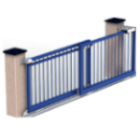 |
If there isn’t enough room alongside the fence to slide a standard cantilever gate open, a two-panel or three-panel telescopic cantilever gate may be the solution. Components and more information about telescopic cantilever gates » |
A few questions and answers about cantilever gates:
1. Can a cantilever gate be installed on a slope?
For an automated cantilever gate, we recommend that the leaf moves horizontally. The ground beneath the gate can slope, but the C-profile, carriages, and travel path should remain level. A gate that travels on a slope requires a bespoke design, a safety assessment, and suitable protection against unintended movement.
The simplest solution is to shape the bottom edge and infill of the leaf to follow the slope, while keeping the support system and operator level. Other solutions need to be designed individually for the specific slope and gate operator.
2. Do the carriages or the inside of the C-profile need lubrication?
No. The bearing carriages and the inside of the C-profile do not normally need lubrication. Remove any dirt that has entered the profile during storage, transport, or use.
3. Why choose a cantilever sliding gate? What are the benefits?
- » low maintenance requirements
- » no ground track across the opening to clear of snow and dirt
- » no work is needed on the roadway
- » the leaf slides alongside the fence; the required clearance behind the gate depends on the specific design
- » a cantilever sliding gate moves above ground and can also be installed on uneven terrain
- » simpler groundwork: there is no need to pour a long foundation for a track (which must be level)
- » there is no track or other obstacle in the opening to impede the gate. In winter, you won’t have to worry about clearing snow and dirt from a track.
- » learn more about cantilever and ground-track gate comparisons »
4. Why do you recommend adjustable pivoting carriages?
The pivoting action helps distribute the load evenly across the bearing rollers as the gate moves. Height adjustment makes it easier to install and level the gate, and to set its clearance above the ground.
5. Which components do customers most often buy in addition to the kit?
For a manual gate, it is mainly hook lock. It is also often supplemented with an upper stop or a second pair of lower stops and an end catcher at the open end. This solution should be tailored to the design, weight and operating conditions of the specific gate.
6. What ground clearance does a cantilever gate have?
The supplied carriages are height-adjustable. If the bottom edge of the carriage is installed level with the surrounding ground, the following table shows the approximate minimum and maximum clearance.
| Opening width / C-profile | C-profile 70x70x4 mm |
C-profile 80x80x5 mm |
|
up to 2.8 m |
Hmin: 78 mm |
Hmin: 73 mm |
| up to 4.5 m carriage with 5 bearing rollers |
Hmin: 95 mm |
Hmin: 90 mm |
| up to 6.5 m carriage with 8 bearing rollers |
Hmin: 90 mm |
Hmin: 85 mm |
The gate's ground clearance can also be adjusted by changing the mounting height of the support carriages. When planning, allow a safe margin for uneven ground, snow and movement of the structure.
7. Where should the rack be secured to the gate?
The rack is most commonly secured to a reinforcing profile above the C-profile. However, its position must match the installation dimensions of the specific drive and maintain proper engagement with the pinion throughout the gate's full travel.
8. At what height should a NICE drive be installed?
Determine the drive height based on the rack position and the dimensions specified in the installation manual for the specific model. The specified clearance must be maintained between the rack and pinion; the drive must not support the weight of the gate.
- use the original base plate and the anchors supplied with the drive, following the installation manual,
- use a suitable steel pedestal or threaded rods designed for the specific drive and anchoring method,
- prepare the pedestal height so the drive can be precisely adjusted and remains accessible for servicing.
9. Which steel profiles should be used to build a cantilever gate?
The most commonly used material is structural steel. Dimensions depend on the overall length, weight, infill and wind load. For typical smaller gates, 60 × 40 × 2 mm profiles are often used, with an 80 × 40 × 2 mm profile as the lower reinforcing member; however, this is not a universal structural design.
Other profile sizes can also be used for the frame. For a larger, heavier or solid gate, we recommend having the design verified by structural calculations or an expert.
For hot-dip galvanizing, the structure must also be designed to accommodate vent and drain holes, the galvanizer's process requirements and the risk of heat-induced deformation. A thicker profile wall can reduce the risk of deformation, but does not eliminate it. Confirm the specific solution with the galvanizer in advance.
| Square hollow section kit for building a sliding gate, 40x40x2 mm | ||
|---|---|---|
| Opening width | Kit name | Kit includes: |
| 3.0 m | JOKL-01 | 2 × 40×40×2 profile – length 6 m 1 × 80×40×2 profile – length 6 m |
| 4.5 m | JOKL-02 | 3 × 40×40×2 profile – length 6 m 1 × 80×40×2 profile – length 6 m |
| Square hollow section kit for building a sliding gate, 60x40x2 mm | ||
| Opening width | Kit name | Kit includes: |
| 3.0 m | JOKL-03 | 2 × 60×40×2 profile – length 6 m 1 × 80×40×2 profile – length 6 m |
| 4.5 m | JOKL-04 | 3 × 60×40×2 profile – length 6 m 1 × 80×40×2 profile – length 6 m |
| 5.5 m | JOKL-05 | 4 × 60×40×2 profile – length 6 m 2 × 80×40×2 profile – length 6 m |
| 6.5 m | JOKL-06 | 4 × 60×40×2 profile – length 6 m 3 × 80×40×2 profile – length 6 m |
| Square hollow section kit for building a sliding gate, 80x40x2 mm | ||
| Opening width | Kit name | Kit includes: |
| 3.0 m | JOKL-07 | 3 × 80 × 40 × 2 profile – 6 m long |
| 4.5 m | JOKL-08 | 4 × 80 × 40 × 2 profile – 6 m long |
| 5.5 m | JOKL-09 | 6 × 80 × 40 × 2 profile – 6 m long |
| 6.5 m | JOKL-10 | 7 × 80 × 40 × 2 profile – 6 m long |
We offer customers the option of buying everything in one place, including the steel materials needed to make the gate. Together with the component set we'll also send you the recommended installation procedure.
Gate infill: The infill can be matched to the style of the fence and house, for example using wooden slats, steel, aluminium or plastic profiles, polycarbonate, or expanded metal. With solid infill, wind load must be taken into account in particular.
10. What cables should be used for NICE operators?
NICE ROAD 400 (RD400)
For NICE ROAD 400 with relay photocells prepare the following cables. Two conductors are sufficient for the TX transmitter; for the RX receiver, we recommend a four-core cable for the power supply and relay contact. This is not a two-wire BlueBUS connection.
| Connection | Cable type | Maximum length |
|---|---|---|
| Operator power supply (230 V) | 1 pc. 3 × 1.5 mm2 | 30 m * |
| Photocell TX (transmitter) | 1 pc. 2 × 0.25 mm2 | 30 m |
| Photocell RX (receiver) | 1 pc. 4 × 0.25 mm2 | 30 m |
| Warning beacon | 1 pc. 2 × 0.5 mm2 | 20 m |
| Antenna | 1 pc. shielded RG58 coaxial cable | 20 m; less than 5 m is recommended |
| Key switch | 2 pcs. 2 × 0.5 mm2 or 1 pc. 4 × 0.5 mm2 | 50 m |
| Fixed safety edge | 1 pc. 2 × 0.5 mm2 | 30 m |
| Moving safety edge | 1 pc. 2 × 0.5 mm2 | 30 m ** |
* For a power cable longer than 30 m, a larger cross-section is required, for example 3 × 2.5 mm2. The appropriate cross-section and protective earthing must be assessed by an electrician based on the installation.
** A moving safety edge requires a device that maintains the connection while the gate leaf is moving. Connect multiple safety edges according to the instructions for the specific operator and edges.
Cables must be suitable for the environment and installation method. Have the wiring and commissioning carried out by a qualified professional. For details, see the NICE ROAD 400 instructions.
NICE RBS400, RBS600 and RB1000
The following indicative wiring applies to the NICE RBS400, NICE RBS600 and NICE RB1000. Always check it against the current manual for the specific model and accessories before installation.
Indicative wiring:
| Connection | Cable type | Maximum permitted length |
|---|---|---|
| A: Power supply (230 V) | 1 pc. 3 × 1.5 mm2 | 30 m (note 1) |
| B: Beacon with antenna |
1 pc. 2 × 0.5 mm2 |
20 m |
| C: Photocells | 1 pc. 2 × 0.5 mm2 | 30 m (note 2) |
| D: Key switch | 2 pcs. 2 × 0.5 mm2 (note 3) | 50 m |
| E: Fixed safety edges | 1 pc. 2 × 0.5 mm2 (note 4) | 30 m |
| F: Moving safety edges | 1 pc. 2 × 0.5 mm2(note 5) | 30 m (note 5) |
Note 1: A power cable longer than 30 m can be used, but it must have a larger cross-section, for example 3x2.5 mm2. Near the device,
grounding must be provided.
Note 2: If the BlueBUS cable is 30–50 m long, use a 2x1mm2 cable.
Note 3: Instead of two 2x0.5 mm2 cables, you can use one 4x0.5 mm2 cable.
Note 4: If you want to use more than one safety edge, read the information on connection types in section 7.3.2, “STOP input”, which
is recommended by the manufacturer.
Note 5: To connect safety edges to the moving gate leaves, special devices must be used that allow the connection to be maintained while the
gate leaf is moving.
Description of the basic components of a cantilever sliding gate
Bearing roller carriages
The carriages run inside the C-channel and support the gate leaf. The pivoting action helps distribute the load evenly across the rollers as the gate moves. The bearings must be protected from dirt and installed according to the manufacturer’s instructions.
C-channel
A heavy-wall, bent structural steel profile supports the gate leaf above the ground and guides it along the support carriages. The frame is welded to it according to the design.
Bottom guide roller
The bottom guide roller is fitted to the end of the C-channel. When the gate closes, it enters the end catch and helps support and stabilize the gate.
End catch
The bottom stop catches the guide roller as the gate closes, supports the leaf, and helps stabilize it against lateral forces.
Upper and side guide
The guide keeps the top of the gate on its designated track. Adjust the rollers to guide the gate reliably without unnecessary friction.
C-channel end cap
The end cap closes the open end of the C-channel on the side without the bottom guide roller.
Electromechanical drive
The drive unit and control electronics automate the gate’s movement. Choose the model according to the gate’s specifications and intended use.
Remote control
The radio transmitter sends the drive receiver a command to open or close the gate, or to perform another programmed function.
Photocells
Photocells are a safety device. When the beam is interrupted, the control unit will stop the gate, prevent it from starting, or reverse its direction, depending on the wiring and programming.
Flashing warning light with antenna
The warning light signals gate movement and, with compatible drives, can flash to help with diagnostics. The integrated antenna improves radio signal reception; it is not a radio receiver.
What next?
» Ask us anything
Email [email protected], and ask us any technical questions about your gate.
» Use the form “Get advice from a sales representative"
Once you provide the basic details of the gate you’re planning, we’ll send you a quote listing the recommended components for a cantilever sliding gate. Find the form HERE.
» View the photo gallery
Photos of DIY projects, built using our components by customers who assembled their gates themselves. Find the photo galleries HERE.
» Why shop with us?
See the benefits of shopping at our store and customer reviews, from customers who have already shopped with us components for a cantilever sliding gate.
If you haven’t found the information you need, get in touch and we’ll be happy to help with your project.
Also read: I have limited space for a cantilever sliding gate. What are my options?
Author: Eng. Ján Kubíček