Anchoring a sliding gate
The sliding gate anchoring is:
- necessary for the sliding gate to operate and move correctly
- it ensures the gate leaf moves in a straight line and is also aligned vertically
- it transfers the forces exerted by the gate support bracket to the concrete foundation, so it must be adequately sized
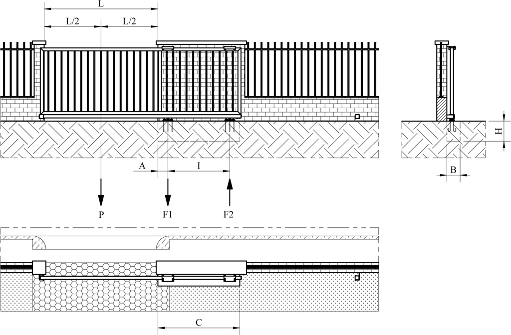
Diagram legend:
A – distance between the center of carriage 1 and the start of the opening L (in m)
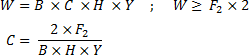
B – width of the concrete foundation (in m)
C – length of the concrete foundation (in m)
H – depth of the concrete foundation (in m)
I – distance between the centers of the carriages (in m)
L – gate opening width (in m)
L/2 – half the opening width L (in m)
P – weight of the gate acting at the midpoint of the opening width
F1 – compressive force acting on carriage 1 (in kg)
F2 – tensile force acting on carriage 2 (in kg)
Y – density of concrete (2400kg/m3)
W – weight of the concrete foundation (in kg)
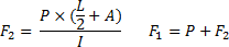
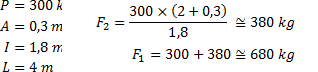
Calculating the maximum load on carriages F1 and F2
Formula
Example
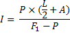
Calculating the distance I between the centers of the carriages
Formula
Example

Calculating the weight W and length C of the concrete foundation
Formula
Example

Coming soon. If you need advice, email us at [email protected].