NICE Spinbus SN6031 – standalone drive for garage doors
| Product availability: | Sale ended | Unfortunately, the product is no longer available for delivery. This does not mean it will never be available again, but at present, it is not expected to be offered for sale again. |
|---|


Description of NICE Spinbus SN6031 – standalone drive for garage doors
NICE Spinbus SN6031 opener is designed for sectional garage doors with an area of 13.5m2, or up-and-over garage doors with a protruding leaf with an area of 12.8m2, or up-and-over garage doors with a non-protruding leaf up to 10.9m2. Which is which? Has a mechanical stop switch. The opener is non-reversible. Full technical specifications ». Download the manual ».
(Is this opener right for me?)
Compare with other openers:
| « Less powerful opener | More powerful opener » |
|---|---|
|
|
|

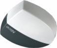
This product—the standalone NICE Spinbus SN6031 garage door opener (our code NICE-SN6031)—includes:
- electromechanical NICE Spinbus SN6031 opener without a control unit SNA3. The opener is supplied without a radio receiver (if you want to operate the door using a remote control, you need to purchase a separate receiver, e.g. SMXI, or OXI).
- installation manual
Discounted kits containing the opener NICE Spinbus SN6031:
| Opener kit with accessories » |
|---|
|
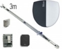
Spinbus SN6031 opener, SNA3 control unit, SMXI receiver, FLO2RE remote control, SNA30 guide rail. |
The opener is compact, safe and practical, making it ideal for both residential and commercial use. Durable plastic housing with built-in lighting.
The opener is suitable for automating a garage door with a door leaf area of 13.5m2 for a sectional garage door, 12.8m2 for a protruding up-and-over garage door, or 10.9m2 for a non-protruding up-and-over garage door. Types of garage doors. These figures apply under the conditions specified by the manufacturer, such as weather conditions, temperature fluctuations, door rigidity and, above all, smooth door movement. These conditions are not always achievable or controllable, so we recommend using the NICE Spinbus SN6031 opener with garage doors at no more than 80% of these values. See the Choosing an opener chapter for more information.
Very user- friendly technology BlueBUS allows to power and control up to 6 pairs of photocells using a two-core cable. The drive also includes a thermal fuse.
Adjustable speed, force and pause time for automatic drive closing and more, see Programming.
Diagnostics using warning beacon.
In the event of a power outage, the drive can be released and the gate moved manually. It is also possible to connect a NICE PS124 backup battery, which allows the drive to perform several operating cycles in the event of a power outage.
The drive control unit has a programmable input, to which you can connect warning beacon, an open-gate indicator, an electromechanical lock, or an electromagnetic lock.
The NICE Spinbus SN6031 drive is an electromechanical operator suitable for Slovakia’s climate and meets all European safety standards.
Accessories compatible with the NICE Spinbus SN6031 drive
We also recommend purchasing compatible optional accessories for the drive, or choosing one of our pre-assembled discounted kits:
| What | Why | Type |
|---|---|---|
| Beacon | The beacon flashes to indicate gate movement—ideal for exits with limited visibility. It also has a built-in antenna for greater remote-control range. | |
| Photocells | They detect obstacles while the gate is closing and stop its movement, preventing the gate from hitting vehicles or people. | - MoonBUS (MOFB) |
| Transmitter |
For remote operation of the gate. |
- FloR (Flo2R-s, Flo4R-s) |
| Receiver | Required for remote operation of the gate. | - OXI - SMXI |
| Antenna | For improved remote-control range. | - built into the beacon LUCYB, MLBT - ABFKIT antenna only, or ABF |
| Keypad | Useful if you forget your remote control, or if many vehicles or people visit and you don’t want to give everyone a remote or open the gate manually. | - MOTXR |
NICE Spinbus SN6031 drive manual
Download the NICE Spinbus SN6031 drive manual here:
NICE Spinbus SN6031 drive manual

NICE Spinbus SN6031 at a glance
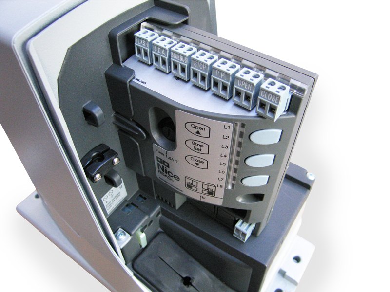 NICE Spinbus is a range of non-reversible electromechanical geared operators for garage doors. They are supplied without a control unit. The compatible control unit is SNA3. The control units have an SM connector for receivers radio signal NICE SMXI, or NICE OXI. Electrical connections for external devices (photocells, warning light, etc.) have been simplified in the NICE Spinbus garage door opener range by using BlueBUS, which allows multiple devices to be connected to a shared terminal using just one two-core cable, with no need to observe polarity. Automatic operation depends on the power supply, but the gear motor can of course be disengaged in the event of a power failure so the gate can be operated manually. It is also possible to purchase an optional NICE PS124 backup battery, which allows the gate drive to be operated even during a power failure.
Choosing a drive – is the NICE Spinbus SN6031 suitable for my gate?
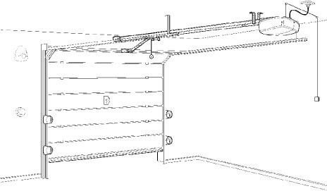
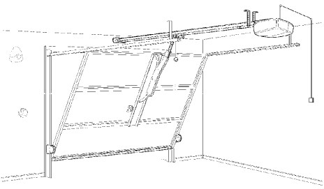
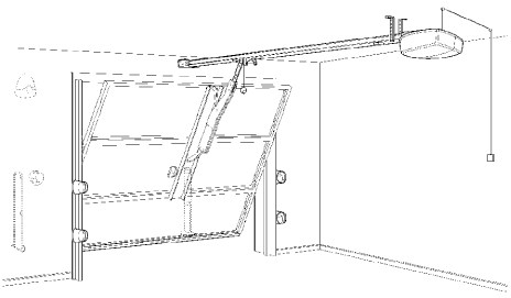
Every gate has its own design (sectional, up-and-over, ...) and area and every drive has its limits. The following types of garage doors are commonly available on the market:
| Sectional garage door | Non-protruding up-and-over garage door * |
|---|---|
 |
 |
| Protruding up-and-over garage door | |
| without springs* | with springs |
 |
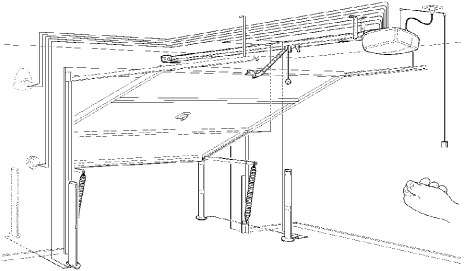 |
* To automate a non-protruding up-and-over garage door or a protruding up-and-over door without springs, you must install a NICE SPA5 swing arm.
The NICE Spinbus SN6031 drive can be used, with the appropriate accessories, for the following areas and door-leaf dimensions:
| Sectional | Up-and-over protruding |
Up-and-over non-protruding |
|
|---|---|---|---|
| max. 13.5m2 | max. 12.8m2 | max. 10.9m2 | |
| 3 m guide rail |
2.4m × 5.0m |
2.8m × 4.2m |
2.2m × 4.2m |
| 4 m guide rail | 3.4m × 3.5m | 3.5m × 3.4m | 3.2m × 2.9m |
In principle, the door-leaf size determines the maximum number of cycles per hour and consecutive cycles, i.e. it indicates how long the drive can operate. Greater force (weight) further reduces this number of cycles proportionally, due to the increased strain on the drive, and also determines the maximum permitted speed for the given load. The drive is equipped with a device (thermal cut-out) that measures both the motor temperature and the ambient temperature, and reduces the number of possible cycles accordingly:
| Cycles per hour Consecutive cycles |
Force required to lift the door leaf* | ||||
| Up to 250N | 250–400N | 400–500N | 500–650N | ||
|---|---|---|---|---|---|
|
H
|
Up to 2m |
20 |
16 |
9 |
5 |
| 2–2.5m | 15 7 |
12 6 |
7 3 |
4 2 |
|
| 2.5–3m | 12 5 |
10 4 |
6 2 |
3 1 |
|
| 3–3.5 m | 10 4 |
8 3 |
5 2 |
2 1 |
|
* 1 kg = 9.81 N, i.e. the force required to lift the door can also be expressed in kilograms by dividing it by 9.81. For example, 500 N is approximately 51 kg.
Installing the NICE Spinbus SN6031 opener
The installation method for the opener varies depending on the installation situation. For a door up to 2.5 m high, use a 3 m guide rail; for a door up to 3.5 m high, use a 4 m guide rail. The guide rail can also be mounted on brackets attached to the ceiling, or fixed directly to the ceiling using NICE SNA16 brackets.
Wiring
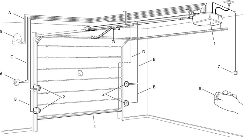
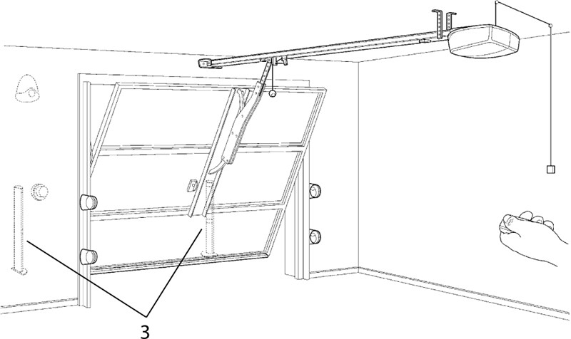
A typical (optional) wiring configuration for an opener with accessories looks as follows for the different types of doors types:
| Sectional garage door | |
|---|---|
 |
|
| Up-and-over garage door with protruding canopy* | Up-and-over garage door without protruding canopy* |
 |
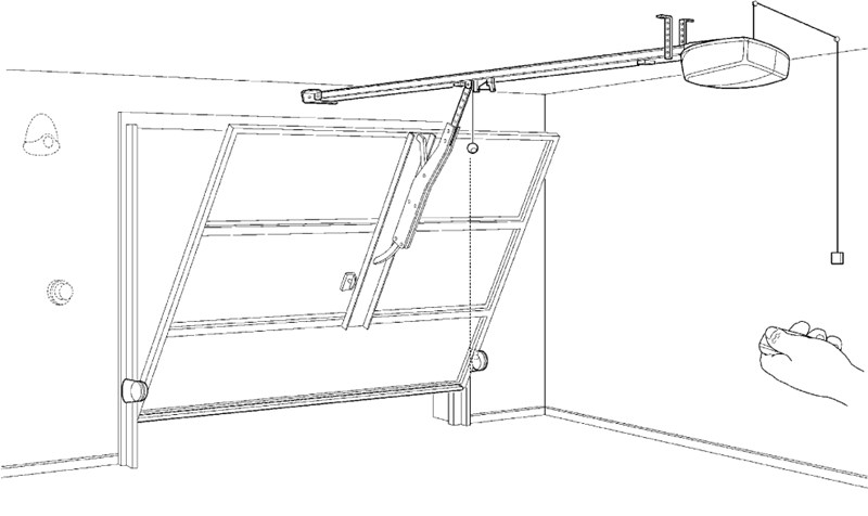 |
* To automate an up-and-over garage door without a protruding canopy, or a protruding up-and-over door without springs, you must install on the door NICE SPA5 swing arm.
Accessories list
|
|
Wiring list
| Purpose | Type | Max. length |
|---|---|---|
| A. Warning light with antenna |
2×0.5 mm2 |
20 m 20 m (recommended: less than 5 m) |
| B. Photocells | 2×0.5 mm2 | 30 m; over 30 m: 2×1 mm2 |
| C. Key switch | 4×0.5 mm2 | 50 m (or 2 pcs. 2×0.5 mm2) |
| D. Safety edge | 2×0.5 mm2 | 30 m |
Installing the NICE Spinbus SN6031 opener
The mechanical installation of the opener itself consists of three steps:
- Pre-installation requirements
- Assembling the guide rail
- Attaching the opener to the assembled rail
- Attaching the rail and opener to the ceiling
0. Pre-installation requirements
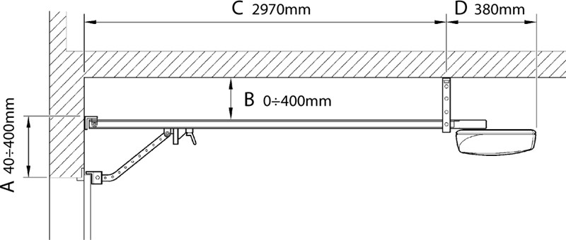
I. Installing the opener requires a certain amount of clearance, particularly for the guide rail. You will need:
- sufficient garage length (C+D) to accommodate the opener (approx. 3.5 m for a 3 m rail, approx. 4.5 for a 4 m rail),
- the clearance between the top point of the door and the ceiling (A) must also be at least 4 cm and no more than 40 cm
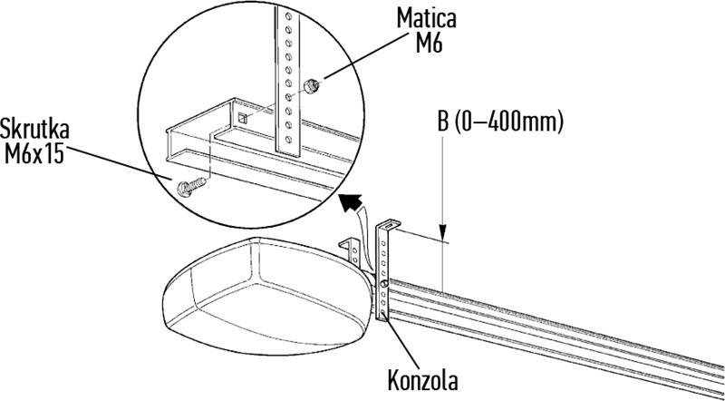
- and the maximum distance between the guide rail and the ceiling (B) should be 40 cm (a shorter distance is fine; the rail can even be mounted directly on the ceiling).
See the illustration for a clearer idea:
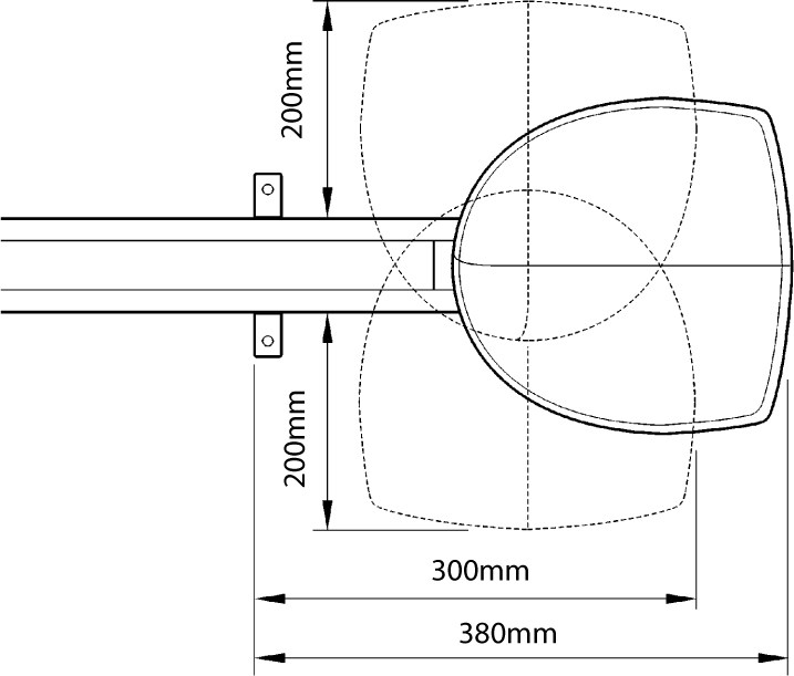
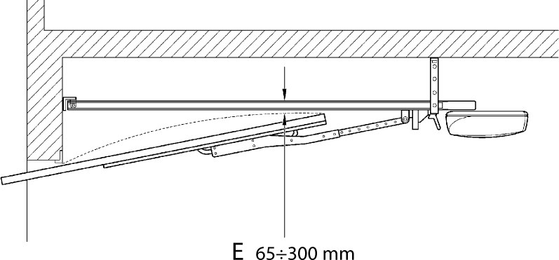
| II. You will also need enough space to install the opener unit itself: | III. For an up-and-over garage door, the difference between the underside of the guide rail and the highest point of the moving door leaf (E) must be at least 6.5 cm and no more than 30 cm when the door is opening: |
 |
 |
Warning: If the above conditions are not met, the NICE Spinbus SN6031 opener cannot be installed, or an alternative mounting solution will need to be devised.
1. Assembling the guide rail
Follow the instructions for the rail you have:
| NICE SNA3X (3×1 m) |
NICE SNA30 (3 m) |
|---|---|
|
|
|


2. Attaching the drive to the assembled rail
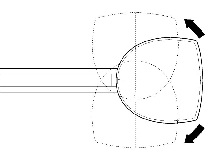
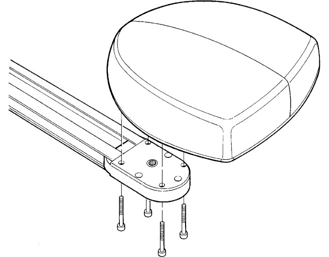
| 1. You can mount the drive in one of three positions, depending on which location best suits your space. | 2. Attach the drive to the drive's rotation-transfer head using the four supplied 6.3 × 38 screws. |
|---|---|
 |
 |
3. Attaching the rail and drive to the ceiling
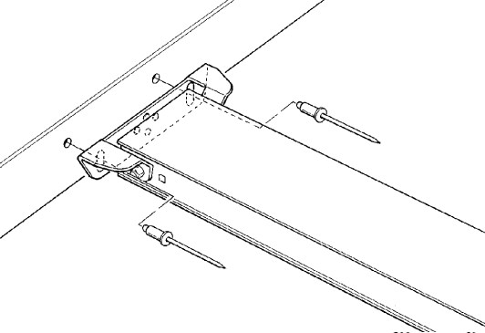
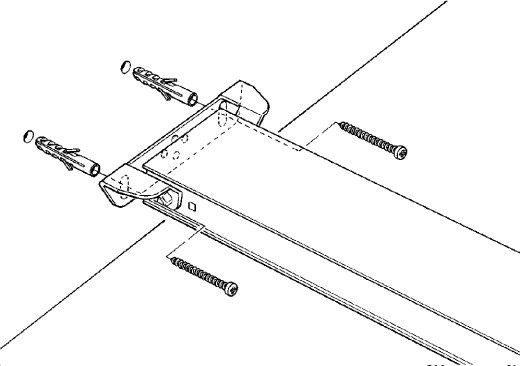
Based on the measured values for the rail's clearance from the ceiling and the top of the gate, mark two mounting holes exactly in the centre of the gate. Depending on the surface, you can attach the front bracket:
| For a profile, you can use rivets. | For a wall, you can use wall plugs and screws. | Alternatively, if the conditions allow, you can attach the rail directly to the ceiling. |
|---|---|---|
 |
 |
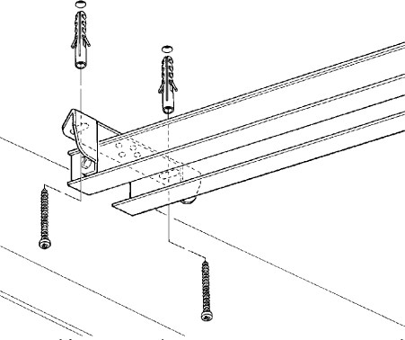 |
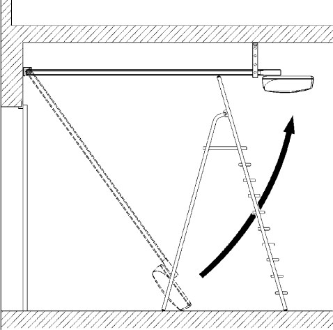
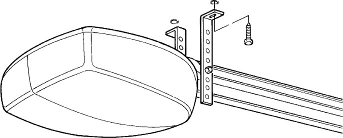
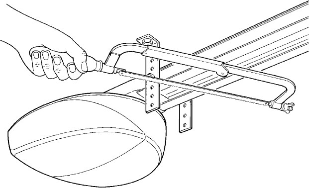
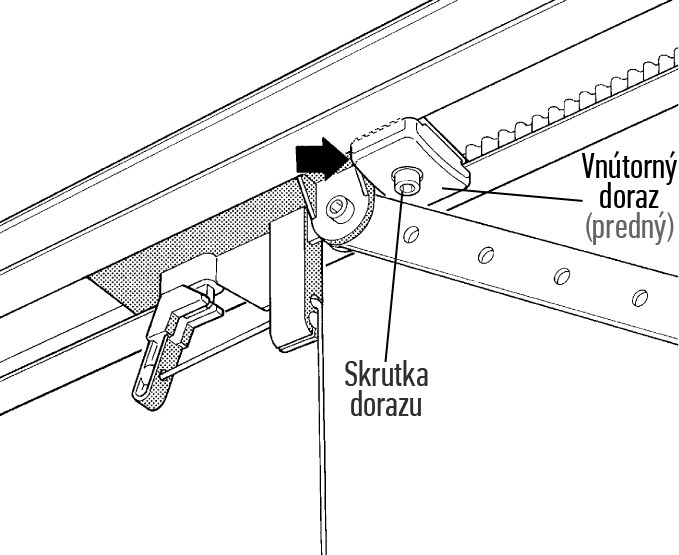
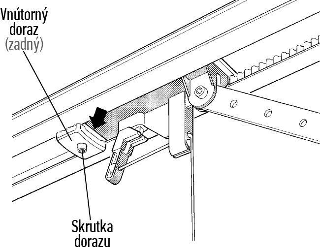
After drilling the mounting holes, attach the front bracket, leaving the other end of the rail with the motor on the ground, then proceed as follows:
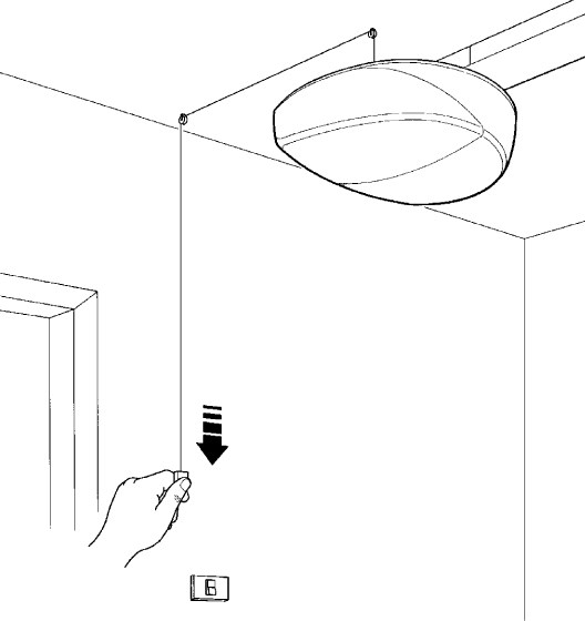
Programming the drive
The programming procedure depends on the control unit supplied. The following control units are compatible with the NICE Spinbus SN6031 drive:
| SNA3 |
|---|
|
|
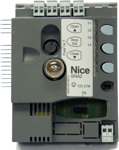
Releasing the NICE Spinbus SN6031 drive
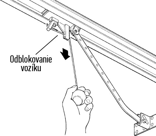
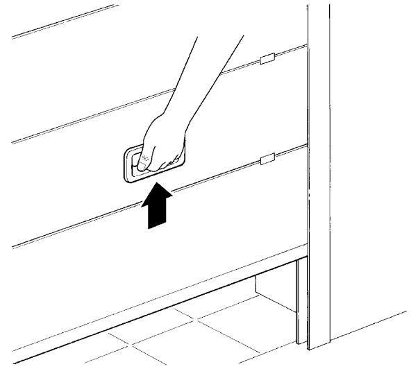
In the event of a power failure, you will not be able to operate the gate using the remote control. Therefore, the drive can be released using the release lever and the gate can be moved manually:
| 1. Pull the trolley release lever. | 2. Move the door leaf. |
|---|---|
 |
 |
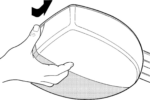
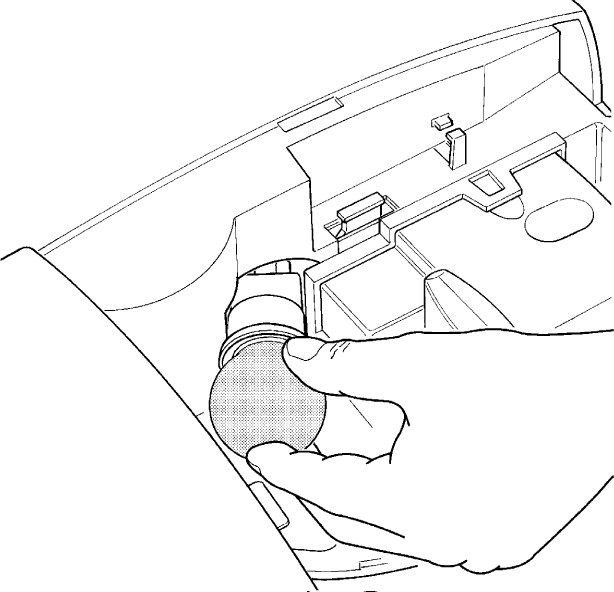
Replacing the bulb in the NICE Spinbus SN6031 drive
Before replacing the bulb, disconnect the drive from the power supply and follow these steps:
| 1. Press the white cover and turn it. | 2. Unscrew the old bulb. Then screw in a new 230V 60W bulb with an E27 base. |
|---|---|
 |
 |
Technical specifications of the NICE Spinbus SN6031 drive
| Model | NICE Spinbus SN6031 | ||||||||||
|---|---|---|---|---|---|---|---|---|---|---|---|
| Description | Electromechanical gear motor for automatic operation of garage doors in private settings. Supplied without a control unit. The compatible control unit is SNA3. | ||||||||||
| Sprocket | Diameter: 9,5mm Number of teeth: 28 Compatible with rails: SNA3X, SNA30, SNA6 |
||||||||||
| Torque [Force] |
14,4Nm [800N] – required to start the door moving |
||||||||||
| Rated torque [Rated force] |
7,2Nm [420N] – required to keep the door moving |
||||||||||
| Speed | 0,20 m/s | ||||||||||
| Rated speed | 0,08 m/s | ||||||||||
| Maximum number of consecutive cycles | 50 cycles/day (the control unit limits the number according to the restrictions; see Choosing a drive) | ||||||||||
| Operating time limit | 3 minutes (the control unit limits the operating time according to the restrictions; see Choosing a drive) | ||||||||||
| Power supply | 230V (+10% -15%) 50/60Hz | ||||||||||
|
Power consumption |
250W (less than 2,2W in standby mode) | ||||||||||
| Insulation class | 1 – must be earthed | ||||||||||
| Backup power supply | can be purchased separately and installed NICE PS124 backup battery | ||||||||||
| Lighting | 230V 60W bulb, E27 socket | ||||||||||
| Flashing light output |
Depending on the programmed output:
|
||||||||||
| BlueBUS output | one output for 6 BlueBUS devices | ||||||||||
| STOP input | for normally open, normally closed, and constant-resistance 8,2KΩ devices | ||||||||||
| STEP-BY-STEP input (P.P., step-by-step operation) | normally open (closing the contact triggers the command “Step-by-step") | ||||||||||
| Radio receiver | without a receiver; “SM” connector for receivers NICE SMXI, NICE OXI etc. | ||||||||||
| Antenna input | 52Ω for RG-58 coaxial cable (or similar) | ||||||||||
| Programming functions | 4 on/off functions (Level I programming.) 4 adjustable functions (Level II programming.) |
||||||||||
| Self-learning functions |
|
||||||||||
| Operating temperature | -20°C to +50°C | ||||||||||
| Use in salty, acidic, and potentially explosive environments | no | ||||||||||
| Protection rating | IP40 – indoor use or well-sheltered outdoor use | ||||||||||
| Dimensions | 311×327×105 (W×D×H) | ||||||||||
| Weight | 4,1kg |
How can I order this item?
Choose the option that suits you:
- order online: use the buy button to add the goods to your shopping cart (you will find the buy button here in the product variants table).
- order by email: place your order at [email protected]