NICE Hyke HK7224 HS high-speed operator
NEW| Product availability: | within 7 days | We usually dispatch goods within 7 days. |
|---|


within 7 days
€792.34 including VAT
| Weight |
|---|
| 13 kg |
Description of NICE Hyke HK7224 HS high-speed operator
NICE HYKE HK7224HS is a fast articulated non-reversible drive for one leaf of a swing gate. It is the second motor, without a control unit; for a double-leaf gate, it must be paired with the HK7024HS. The HK7224HS on its own is not a complete drive for a single-leaf gate.
The motor operates on 24 V DC. It is powered and controlled by the built-in control unit in the HK7024HS; the HK7224HS must not be connected directly to a 230 V mains supply. The articulated arm can also be installed when the hinge is offset on a wider mounting surface, provided the position and clearance comply with the installation diagram. With a standard installation, opening to 90° takes approximately 10 s.
| Quick navigation | |
|---|---|
| Choosing a drive | Accessories |
| Installation | Arm and stops |
| Wiring | Terminals |
| Initial startup | Programming |
| Diagnostics | Reset |
| Maintenance | Service life |
| Specifications | PDF manual |
Choosing a drive and leaf limits
HYKE HS has separate maximum limits for 3 m length and 270 kg weight. These limits do not apply simultaneously: the permissible combination is determined by the graph. According to the graph, a 3 m leaf can weigh approximately 175 kg; a 1.8 m leaf, approximately 260 kg. Therefore, a length of 3 m and a weight of 250 kg are not a permissible combination for a single leaf. Solid infill, wind, poor balance or resistance to movement can lower the limit further.
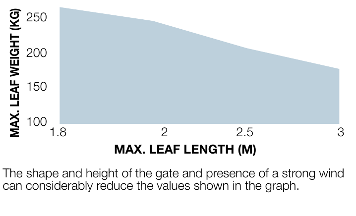
The graph shows leaf length on the horizontal axis and weight on the vertical axis single leaf.
With the shortened arm, the operating range is smaller than with the full-length arm. Before choosing a drive, check that the gate moves freely, the leaf is rigid and the arm can be positioned safely. One motor is required per leaf; two motors do not increase the permitted weight of a single leaf.
Control system and compatible accessories
| What | Why | Type |
|---|---|---|
| Motor and control system | One motor per leaf. The drive requires HK7024HS to control the complete double-leaf gate system. |
|
| Radio receiver | SM connector on the HK7024HS control unit; choose a receiver to match the transmitter coding. | |
| Remote control | Pair it with the installed receiver; frequency alone does not determine compatibility. | |
| Photocells | Safety devices on BlueBUS; run the learning procedure after adding them. | |
| Warning light | Indicates movement. The FLASH output is 12 V DC / max. 21 W. | |
| Backup power supply | For the HK7024HS in the event of a mains failure, after checking the control board and connector. |
|
Installation and site inspection
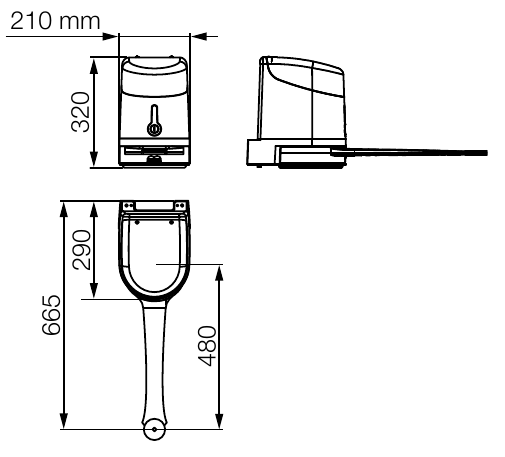
The substrate must safely support the bracket, and the arm must move freely through its entire range of travel. Allow at least 210 mm of clearance. For the installation shown, the distance from the motor axis to the opposite obstruction must be at least 300 mm; measure the additional 150 mm dimension and hinge offset according to the relevant drawing. These are not universal post dimensions. A hinge offset of up to approximately 400 mm is possible only with geometry that matches the drawing and chart. Choose the bracket anchors to suit the actual substrate; they are not included with the motor.
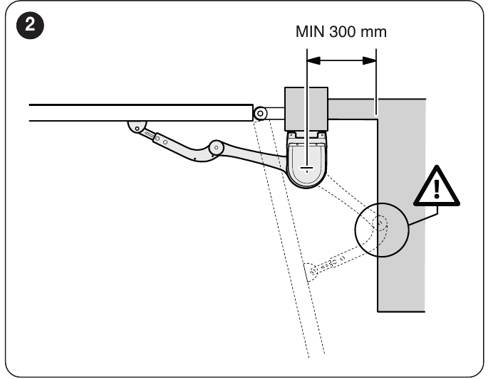
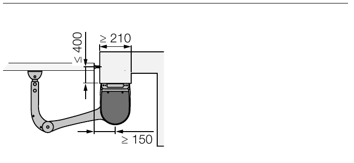
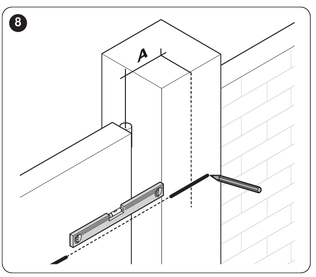
Before drilling, measure the hinge-axis and bracket positions and the required angle. For the full-length arm, use the original A/B dimension chart; secure the gate-leaf bracket to a rigid part of the frame. With the full-length arm, the maximum opening angle is 110°, according to the installation chart. Repair the gate first if it binds, is deformed, or lacks rigid stops.
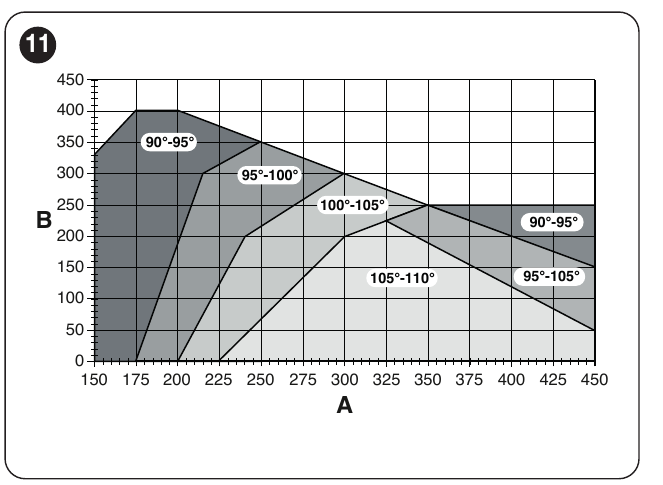
Full-length and shortened arms, end stops
At the obstruction, measure the available clearance E. Use the full-length arm when E is at least 650 mm; if E is 300–650 mm, shorten it according to the installation instructions. The shortened arm limits the permitted angle and the combination of length and weight; for this configuration, refer to the chart and do not exceed the planned opening angle. Shorten the arm only at the specified points on the original arm; do not estimate the cut.
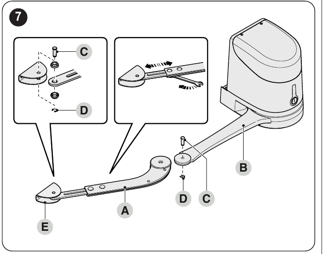
After securing the motor, position the arm and gate-leaf bracket at the furthest rigid point, check that the arm engages correctly in its end position, and adjust the mechanical opening and closing stops. With the motor disengaged, move the gate manually through its entire range; it should move easily and without collisions.
Electrical connections
This motor connects to the M2 output of the HK7024HS control unit and its encoder to ENC2; terminals M1/ENC1 are for the first motor. Check the gate-leaf sequence during learning. The control unit supplies 24 V DC; do not connect the motor directly to the mains. Disconnect both the mains supply and the backup power source before working on the system. For the second motor, use 3 × 1.5 mm² cable up to 10 m and 2 × 1 mm² encoder cable up to 10 m; the actual cable route and cross-section must suit the installation.
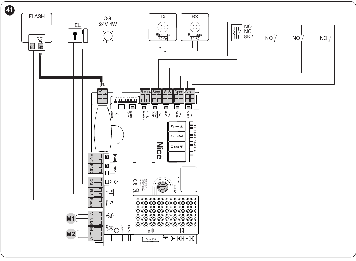
Accessory power supply and polarity
| Terminals | Connection |
|---|---|
| BlueBUS | Two wires for compatible photocells; no polarity. Repeat the learning procedure after changing devices. |
| SbS (+) and STOP (−) | Auxiliary 24 V DC, maximum 200 mA between the terminals marked as shown on the integrated control board. Voltage remains present in standby mode. These terminals also serve as command and safety inputs; accessory power must be connected in accordance with the contact wiring. |
| STOP, SbS, OPEN, CLOSE | Voltage-free contacts; STOP can be NO, NC or 8.2 kΩ resistance, depending on the learning procedure. No +/− polarity applies to the contact itself. |
| ENC1 / ENC2 | Encoder for the corresponding motor; follow the manual no polarity. |
| FLASH | 12 V DC, maximum 21 W; select a warning light to suit the operating mode and power consumption. Do not guess the polarity of individual unmarked terminals. |
| ELS / OGI | ELS: 12 V AC lock, maximum 15 VA. OGI: 24 V DC indicator, maximum 4 W. Outputs may change function when programmed. |
First start-up and position learning
The HK7224HS has no programming buttons or built-in control unit. The HS type, position learning and operating functions are set on the control board in the HK7024HS. The following steps apply only to this configuration with the 12-position switch shown in the diagram.
When connected to the HK7024HS, first have the integrated control board recognize BlueBUS and STOP, then set the HYKE HS switch and learn the end positions. For a dual-leaf gate, the control unit must correctly identify M1 and M2. If the initial movements or sequence are incorrect, stop the learning procedure and check the motor and encoder wiring.
Programming on the integrated control board
Functions are set only on the motor's integrated control board HK7024HS. When replacing the control board, check its actual markings and switch layout.
Diagnostics
On the HK7024HS, BlueBUS flashes approximately once per second during normal operation. Slow flashing of L1/L2 indicates changed or unlearned devices; slow flashing of L3/L4 indicates unlearned positions or switches changed after learning. Learn the positions again. A STOP LED that is off indicates that the safety input has been triggered. For the second HK7224HS motor, check these indicators on the first drive with the control unit.
In the event of a fault, the FLASH light repeats a group of short flashes, then repeats the group after a 1-second pause. Count the flashes in one group.
| Number of FLASH light flashes | What to check |
|---|---|
| 1 | BlueBUS device changed or disconnected; after fixing the issue, repeat device learning. |
| 2 | Photocell or an obstruction in its beam. |
| 3 | Increased resistance to movement or force setting; check the mechanism first. |
| 4 | STOP active or a change to the learned safety input. |
| 5 | Control unit internal parameter error; wait at least 30 s, then try the command again. If the issue persists, disconnect and restore the power supply; contact service if it happens again. |
| 6 | The limit for consecutive cycles or cycles per hour has been exceeded; wait a few minutes for the limiter to allow movement again. |
| 7 | Electrical circuit fault; wait at least 30 s, then try the command again. If the fault persists after restoring the power supply, contact service. |
| 8 | Another continuously active command is preventing movement; check the control inputs and the cause of the held command. |
| 9 | The gate was locked by a command; unlock it using the appropriate control command. |
| 10 | The encoder detected an obstruction or high friction; check the gate-leaf travel path. |
Restoring settings
On the HK7024HS integrated control board, press and hold Open and Close, until L1 and L2 start flashing, then release the buttons. This restores the factory programming values; custom settings will be lost. After resetting, check the wiring and control board indicators; if the unit requests new device or position learning, complete it before operation.
Manual release and maintenance
If the power fails, release the motor using the supplied key and lever turned 90°, then move the gate leaf by hand. Re-engage the motor before resuming automatic operation. A technician must carry out maintenance no later than after 6 months or 20,000 operations: check for wear, secure brackets, stops, free gate movement and safety devices.
Estimated service life
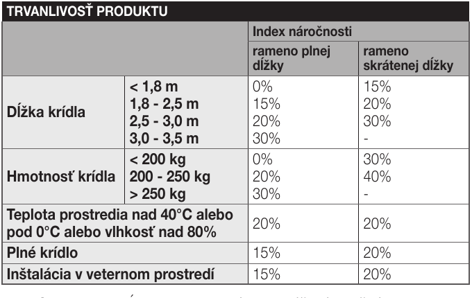
The duty index is the sum of the effects of length, weight, full-length or shortened arm, temperature/humidity, solid gate leaf and wind. The manufacturer's values are indicative and do not guarantee a number of cycles. First check that the length and weight combination is permitted in the HYKE HS chart above; only then use the index to estimate service life. The cycle-count chart is not a guarantee.
| Specifications of the complete automation system | Index | Service life graph |
|---|---|---|
|
| |
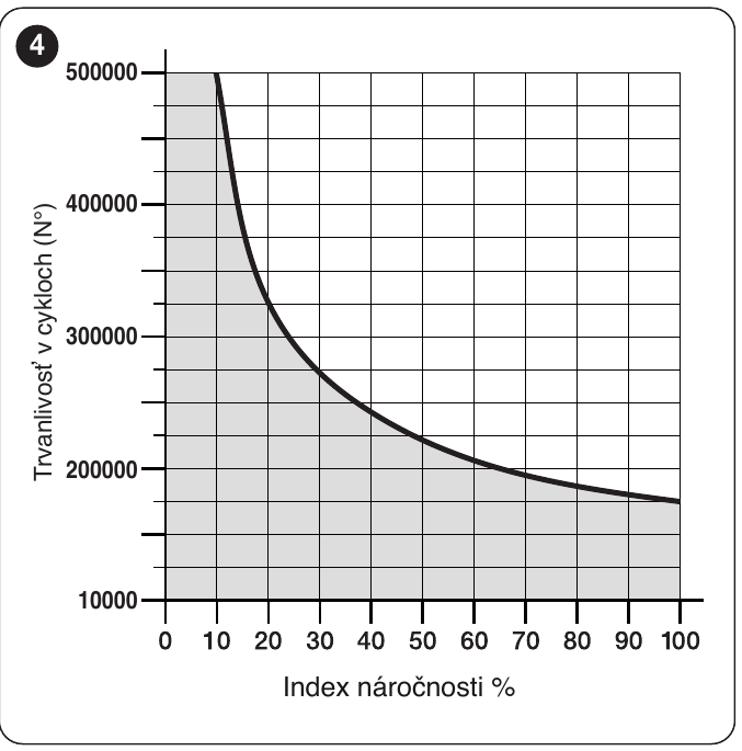
Technical specifications and dimensions
| Parameter | Value |
|---|---|
| Model | NICE HYKE HK7224HS |
| Application | High-speed articulated operator for one gate leaf; HK7224HS is the second motor, without a control unit. |
| Motor voltage | 24 V DC |
| Power supply | 24 V DC from the HK7024HS control unit; no separate mains connection. |
| Power consumption / current draw | 140 W; up to 6 A for short periods (max. 2 s). |
| No-load speed | 2 rpm; 90° takes approximately 10 s under standard installation conditions, without acceleration or deceleration. |
| Starting / rated torque | 500 / 120 Nm. |
| Operation | Up to 40 cycles/h at rated torque; continuous operation for no more than 7 min. |
| Operating temperature | −20 to +50 °C according to the current catalogue. |
| Ingress protection rating | IP54 with the cover intact. |
| Motor dimensions | 290 × 210 × 320 mm. |
| Motor weight only | 9.5 kg. |
How can I order this item?
Choose the option that suits you:
- order online: use the buy button to add the goods to your shopping cart (you will find the buy button here in the product variants table).
- order by email: place your order at [email protected]