NICE Toona TO6024HS – fast 24 V swing gate operator
NEW| Product availability: | within 7 days | We usually dispatch goods within 7 days. |
|---|


within 7 days
€839.38 including VAT
| Weight |
|---|
| 12 kg |
Description of NICE Toona TO6024HS – fast 24 V swing gate operator
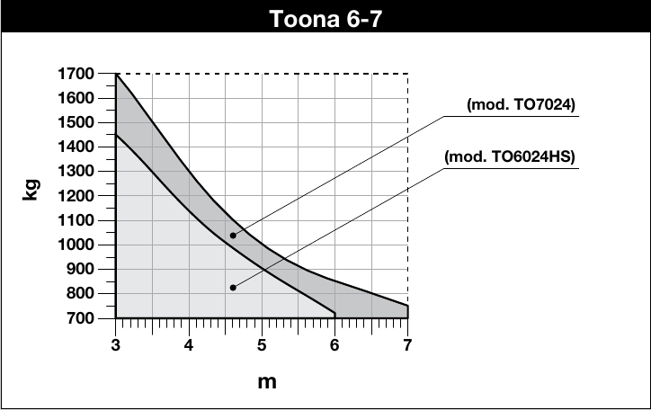
NICE Toona TO6024HS is a fast standalone actuator for one gate leaf, with a 24 V DC and a magnetic encoder. The maximum ratings 6 m and 1,450 kg must be assessed together using the load curve.
NICE specifies an opening time of approximately 30 seconds to open through 90° with standard installation, excluding acceleration and deceleration. The actual time depends on the geometry, gate leaf and control unit settings. The actuator is sold separately; accessories and controls must be selected separately.
| Quick navigation | |
|---|---|
| Package contents | Accessories |
| Kits | Limits |
| Service life | Installation |
| Wiring | Stops |
| Testing | Manual release |
| Specifications | Maintenance |
| Manual | |
| Accessories – terminals and polarity | PDF manual |
What is included with the actuator
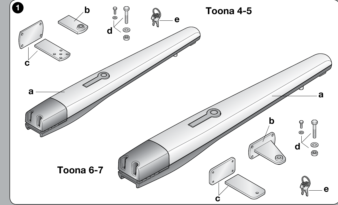
In the lower part of the original image labelled Toona 6–7 are the motor, front bracket, rear bracket with plate, mounting hardware and manual release keys. The exact number of small parts depends on the supplied package; the control unit and safety accessories are selected separately.
Wiring accessories with the MC824HR30
The following terminals belong to the MC824HR30/MCA1R30 control unit in an assembly with the TO6024HS motor, not to the motor itself. Disconnect the mains supply and backup battery before working. For a different board, use its own wiring diagram.
| Accessories | Terminals, voltage and polarity |
|---|---|
| BlueBUS photocells | Connect compatible photocells, such as EPMB, using a two-wire connection to BlueBUS. + and − polarity does not matter. Set the address and repeat the learning procedure whenever devices are changed. |
| STOP and commands | Input STOP accepts a voltage-free NO or NC contact, or a resistive device 8.2 kΩ; its status is learned. SbS, Open and Close accept voltage-free NO contacts on the corresponding pair of terminals. Contacts have no +/− polarity; do not apply an external voltage to the input. |
| Auxiliary power supply | Right terminal of the STOP pair = −; left terminal of the SbS pair = +, in the orientation shown in the image below (labels above the terminals). Power supply for a compatible reader or module: 24 V DC (−30% to +50%), max. 200 mA, including in Stand-by mode. Wire the module's command relay separately as a voltage-free contact; check the permitted voltage range and the module's current draw. |
| Flashing light, lock, indicator light | FLASH: 12 V DC, max. 21 W; ELS: 12 V AC, max. 15 VA, no fixed +/− polarity; OGI: 24 V DC, max. 4 W. For FLASH/OGI, the diagram does not specify the +/− order on the terminal pair, so do not assume it; for a polarised product, check the markings on both the board and the product. Outputs may have different functions depending on programming. |
| Radio receiver and backup power | The plug-in receiver fits into the SM, and the backup battery into its dedicated connector, as indicated on the installed board. They are not connected to BlueBUS or the motor terminals. |
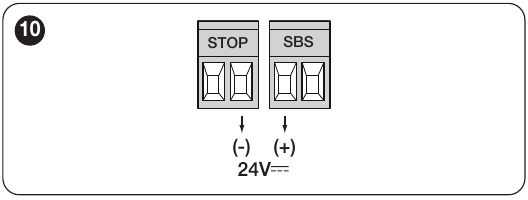
For detailed terminal locations, the learning procedure and testing of safety devices, see the MC824HR30 control unit manual.
Control unit and accessories
The standalone motor requires a compatible control unit. The current MC824HR30/MCA1R30 controls one or two 24 V motors and has its own manual; for the older MC824HR10/MCA1R10, use the manual for its board. Check the contents of the selected kit to confirm exactly what is included.
| What | Why | Type |
|---|---|---|
| Control unit | Controls a 24 V motor; select the manual for the board actually installed. | |
| Receiver | Choose the radio receiver to match the transmitter coding and control board. | |
| Transmitter | Choose one to match the receiver; BD and LR modes require the corresponding receiver. |
|
| Photocells | Select based on the BlueBUS inputs, power supply, and features of the specific control unit. | |
| Warning light | The voltage, power consumption, and flashing mode must match the control unit output. |
Kits with the TO6024HS operator
Separate kits are available for both single- and double-leaf gates. Before ordering, check the actual kit contents and control board on the specific product page.
| Single-leaf gate | Double-leaf gate |
|---|---|
| Kit with accessories Kit with photocells Basic kit | Basic kit Kit with accessories Kit with photocells |
Operating range for one leaf
Length and weight are joint limiting factors. Curve TO6024HS supports approximately 1,450 kg at 3 m and approximately 700 kg at 6 m. Use only the curve for your model, and take into account movement resistance, a solid infill, and wind; the maximum figures cannot simply be combined.
Service life based on load
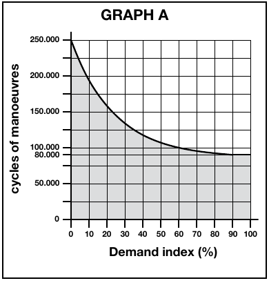
For one leaf, add the relevant weight, length, and environmental indices. Then compare the total with the NICE chart. The chart does not provide a value above 100%. This is an indicative service-life estimate of 80,000 to 250,000 operating cycles depending on the load, not a guarantee.
| Properties of the complete automation system | Index | Service-life chart |
|---|---|---|
| Weight up to 400 kg | 0% |
|
| Over 400 kg up to 500 kg | 10% | |
| Over 500 kg | 20% | |
| Length 2–3 m | 0% | |
| Length 3–4 m | 0% | |
| Length over 4 m up to 5 m | 10% | |
| Length over 5 m up to 6 m | 20% | |
| Temperature above 40 °C, below 0 °C, or humidity above 80% | 20% | |
| Solid gate-leaf infill | 15% | |
| Windy area | 15% |
| NICE chart |
|---|
Installing the operator and brackets
Before installation, check that the gate is structurally sound, the leaf moves smoothly by hand, there is room to release the operator, and there is a suitable mounting point on a rigid part of the leaf. Have installation and electrical connections carried out by a qualified technician.
Rear bracket mounting and the A/B/C chart
Post and brackets: As a general guideline, we recommend a sturdy steel post 120 × 120 mm. For 100 × 100 mm the installer must separately assess the wall thickness, anchoring, foundation, hinge offset, and wind load. The cross-section alone does not guarantee strength.
Measure the hinge offset C. On the original TO6024HS/TO7024 chart, draw a horizontal line from C and read off B; the intersection with the recommended line r.i.l. determines the angle and the vertical line gives A. Dimensions A and B should be similar. B values below the line t are not recommended by NICE.
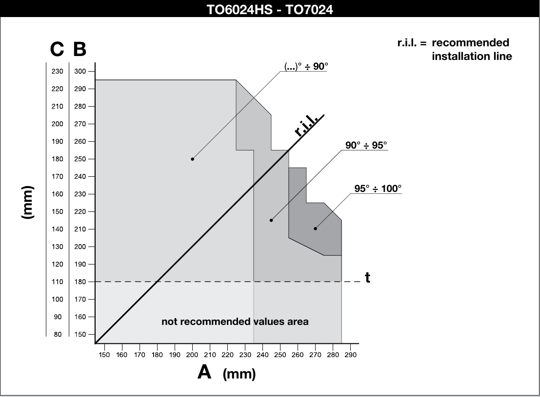
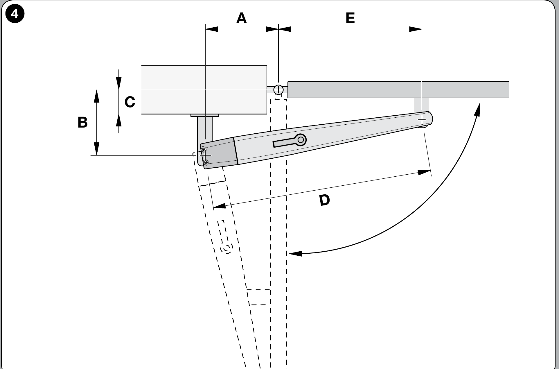
If the post profile or hinge position prevents you from following the chart, the rear bracket must be modified or a suitable extended mounting bracket for Toona 6–7. An extended rear mounting bracket is required when the gate opens outward. Choose the dimensions to suit the actual gate and check the full range of movement before making the final weld.
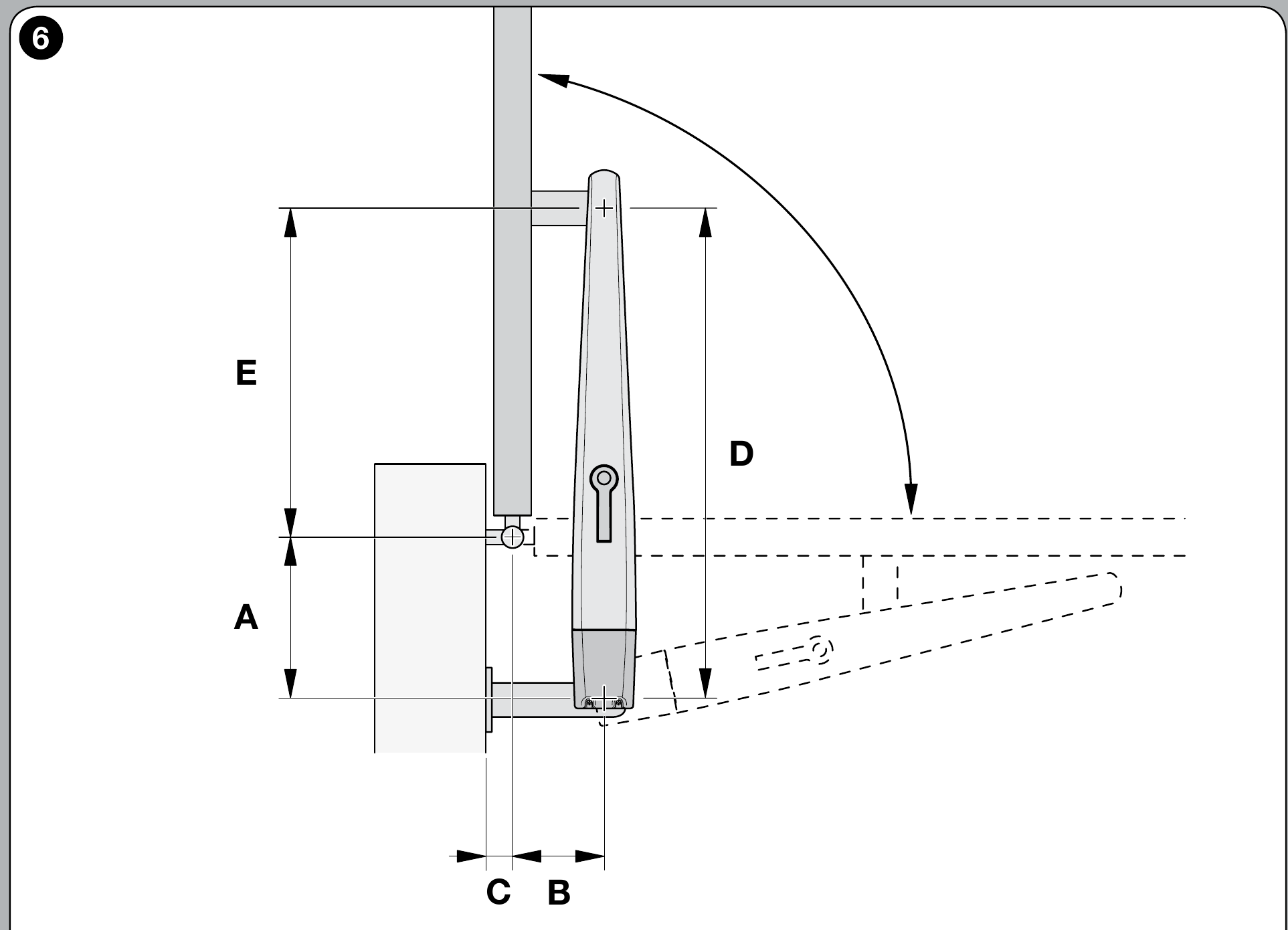
After checking the geometry, securely fasten the rear bracket to the mounting plate and post. Choose fasteners for the post to suit the substrate. Fasten the front bracket to a rigid part of the leaf; the motor must have the required small amount of play at the pins to prevent binding.
Dimension D = 1,070 mm. After determining A from the graph, read off E in the NICE table; the height difference between the front and rear brackets is F = 50 mm.
| A (mm) | E (mm) |
|---|---|
| 180 | 890 |
| 190 | 880 |
| 200 | 870 |
| 210 | 860 |
| 220 | 850 |
| 230 | 840 |
| 240 | 830 |
| 250 | 820 |
| 260 | 810 |
| 270 | 800 |
| 280 | 790 |
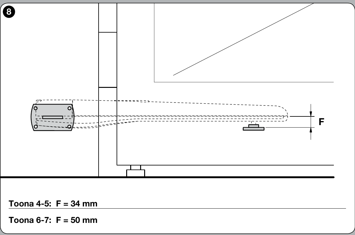
For the rear pin, NICE specifies that the nut should be tightened and then loosened by 1/10 of a turn, leaving minimal clearance between the parts. Tighten the front fixing according to the manufacturer's drawing.
Motor wiring and connections
Before opening the cover and making connections, disconnect the power supply. The drive has separate terminals for the encoder and 24 V DC motor; do not confuse them. Connect the wires and protective earth according to the original NICE diagram and the instructions for the control unit actually installed. The 24 V rating is the motor voltage, not necessarily the mains supply voltage for the control unit.
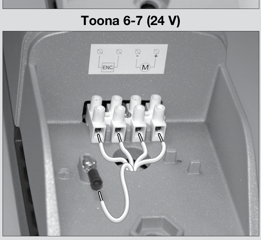
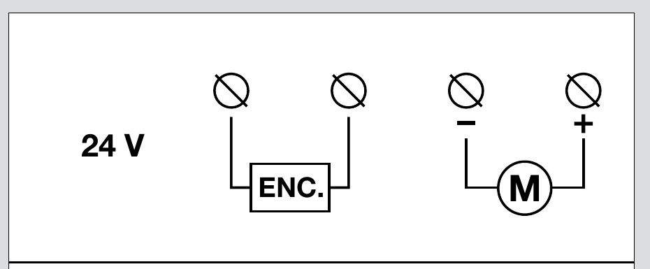
When opening outwards, NICE specifies that the motor supply polarity must be reversed. At the same time, the mounting geometrymust be designed correctly; changing the wires alone is not enough. Then check the direction of movement, stop positions and safety devices according to the instructions for the control board installed.
Internal opening and closing stops
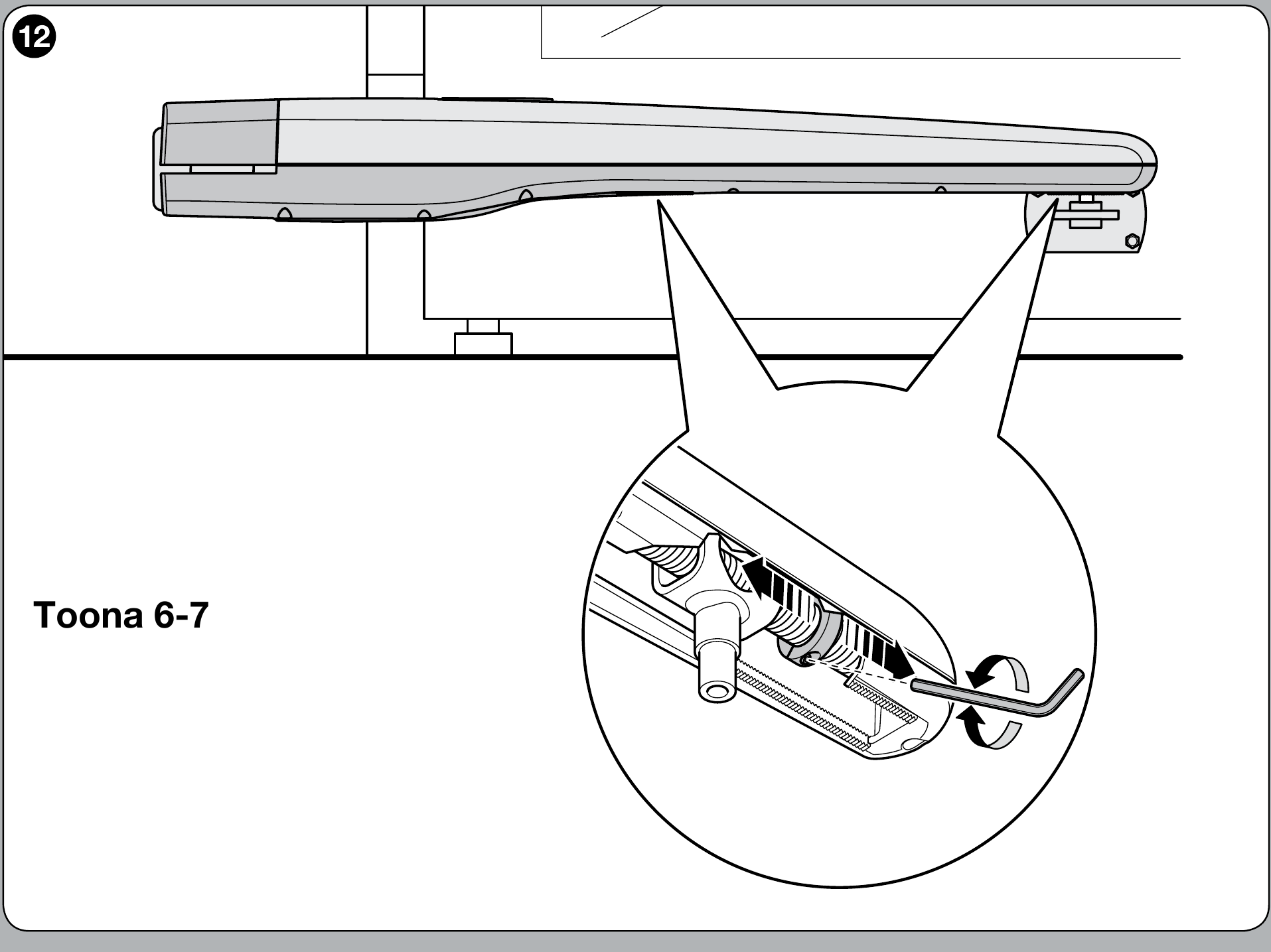
On the Toona 6–7 series, the mechanical stops are adjusted for both opening and closing. Release the motor, move the gate leaf until the stop screw is accessible, loosen it, manually set the desired open position, move the stop up to the pin and tighten it. Repeat the same procedure at the desired closed position, then lock the motor. Check the final positions and the safety of the entire gate during testing.
Testing before first use
After installation and adjustment of the stops, a qualified technician must test the entire gate, not just the motor starting. With the drive released, NICE specifies checking manual movement of the gate leaf using a force of no more than 390 N.
- Check that the gate moves smoothly by hand throughout its full travel, that the brackets are secure and that the release mechanism works safely.
- Issue repeated open, stop and close commands; check the direction, run-on, stops and, for a double-leaf gate, the sequence according to the control unit instructions.
- Check the photocells, safety edges and any other installed safety devices individually. The technician must measure the operating forces in accordance with applicable requirements; the gate may be used only after it has passed the test.
Manual release of the drive
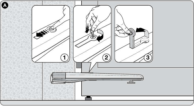
Release or engage the drive only when the gate leaf is stationary. If an electric lock is installed, unlock it first. In the event of a fault, disconnect the power supply.
- Slide back the cover of the release lock.
- Insert the supplied key and turn it clockwise.
- Lift the lever and move the gate leaf by hand. To re-engage the drive, lower the lever, turn the key back, remove it and close the cover.
Inspection and maintenance
Serviced at least every 6 months by a qualified technician. After disconnecting the power supply, the technician checks the fastenings, corrosion, wear, screw connections and lubrication of the lead screw and nut. After switching on the power, the technician tests movement, release and all safety devices.
Technical specifications
| Parameter | Value |
|---|---|
| Model | TO6024HS |
| Motor voltage | 24 V DC |
| Maximum / rated current draw | 5 A / 2.5 A |
| Maximum / rated power input | 120 W / 60 W |
| Stroke | 584 mm |
| No-load speed | 0.016 m/s |
| Maximum / rated force | 2 200 N / 1 200 N |
| Cycles per hour at rated force | 41 |
| Protection rating | IP44 |
| Operating temperature | −20 to +50 °C |
| Insulation class | F |
| Estimated service life | 80,000 to 250,000 cycles depending on load |
| Dimensions L × W × H | 1 200 × 128 × 150 mm |
| Motor weight | 15 kg |
How can I order this item?
Choose the option that suits you:
- order online: use the buy button to add the goods to your shopping cart (you will find the buy button here in the product variants table).
- order by email: place your order at [email protected]