NICE Toona TO5024HS – fast standalone 24 V swing gate operator
NEW| Product availability: | within 3 days | We usually ship the goods within 3 days. |
|---|


within 3 days
€498.92 including VAT
| Weight |
|---|
| 9,55 kg |
Description of NICE Toona TO5024HS – fast standalone 24 V swing gate operator
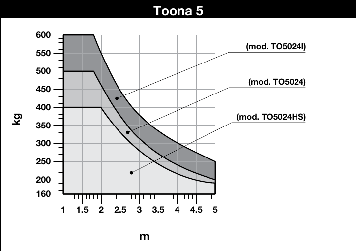
NICE Toona TO5024HS is a high-speed, standalone 24 V DC motor for one gate leaf. The figures of up to 5 m and up to 400 kg are separate maximum values; determine the permitted combination from the TO5024HS curve.
NICE specifies an opening time of approximately 16 seconds for a standard installation, excluding acceleration and deceleration. The actual time depends on the geometry, gate leaf and control unit settings. The 24 V rating refers to the motor; for the current MC824HR30/MCA1R30 follow the manual for this control board.
| Quick navigation | |
|---|---|
| Package contents | Limits |
| Service life | Installation |
| Wiring | Stop |
| Accessories | Control unit |
| Manual release | Specifications |
| Maintenance | PDF manual |
| Accessories – terminals and polarity | |
- High-speed version HS: 0.025 m/s unloaded; 0.018 m/s under load.
- One gate leaf up to 5 m and 400 kg, only in a combination permitted by the TO5024HS graph.
- Internal opening stop, manual release and separate encoder wires.
What is included with the standalone operator
| NICE-specified component | Purpose |
|---|---|
| TO5024HS motor | Drives one gate leaf. |
| Front and rear brackets with mounting plate | Attachment to the gate leaf and post. |
| Fasteners and release keys | Mounting the operator on the brackets and manually moving the gate during a power failure. |
The exact number of parts depends on the supplied version; check the package contents against figure 1 in the NICE manual. Anchor bolts and wall plugs for the post or wall are supplied separately, as appropriate for the substrate. Choose the control unit and safety accessories to suit the specific system configuration.
Operating range
TO5024HS: the 400 kg limit applies approximately to a gate leaf up to 2 m; at 5 m, the graph indicates approximately 190 kg. Also consider resistance to movement, the gate leaf infill and wind. The graph shows the operating limit; it is not a guarantee of service life.
Service life based on load
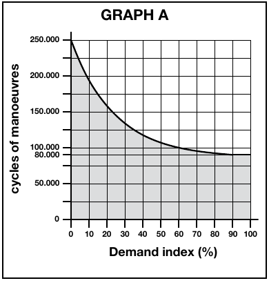
For each gate leaf, add the relevant indices for weight, length and environmental conditions. Read the estimated number of cycles from the original graph. This calculation is the manufacturer's estimate, not a service-life guarantee.
| Characteristics of the complete automation system | Index | Service-life graph |
|---|---|---|
Weight up to 300 kg | 0% |
|
Over 300 kg up to 400 kg | 10% | |
Length 2–3 m | 0% | |
Length over 3 m up to 4 m | 10% | |
Length over 4 m up to 5 m | 20% | |
Temperature above 40 °C, below 0 °C or humidity above 80% | 20% | |
Solid gate leaf infill | 15% | |
Windy area | 15% |
| NICE graph |
|---|
Choosing a control unit
Current model: MC824HR30/MCA1R30. For an older system, check the control board model; the manual for the new board does not automatically apply to an older one. The motor is also sold separately, so check the contents of the specific kit.
If you are unsure which control board or mounting geometry to choose, contact technical support.
I. Installing the rear mounting bracket
Bracket attachment: For a typical steel structure, a 120 × 120 mm post is recommended as a general guide. A 100 × 100 mm profile may be used after assessing the material, wall thickness, height, foundation, anchoring and wind load. The post dimensions alone do not confirm that the installation will be strong enough.
Measure the hinge offset C, then use the original installation graph to determine B, the opening angle and A. A and B should be similar; NICE does not recommend B values below the line t NICE does not recommend this. If the post or hinge offset does not allow the geometry to be maintained, adjust the bracket or use the extended PLA6 rear bracket. An extended rear bracket is required for outward opening; determine the dimensions based on the actual gate. Before welding, measure the supplied brackets and check the gate leaf's full range of movement.
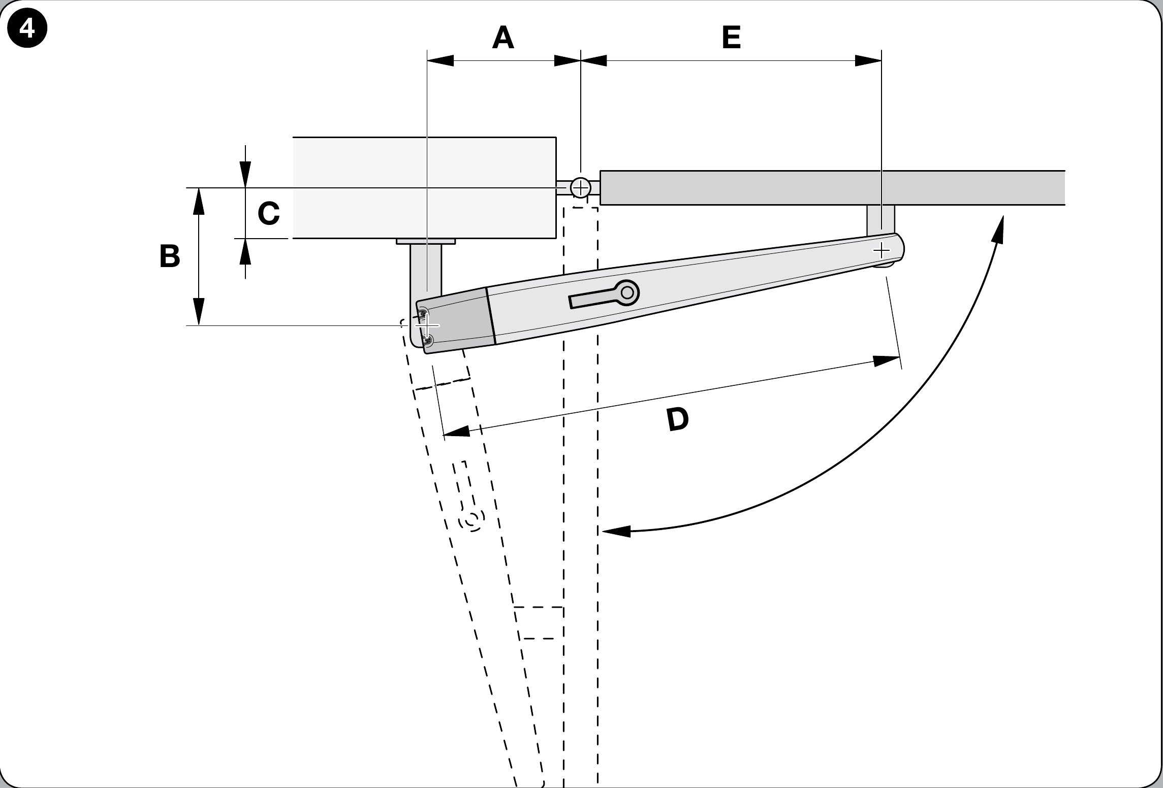
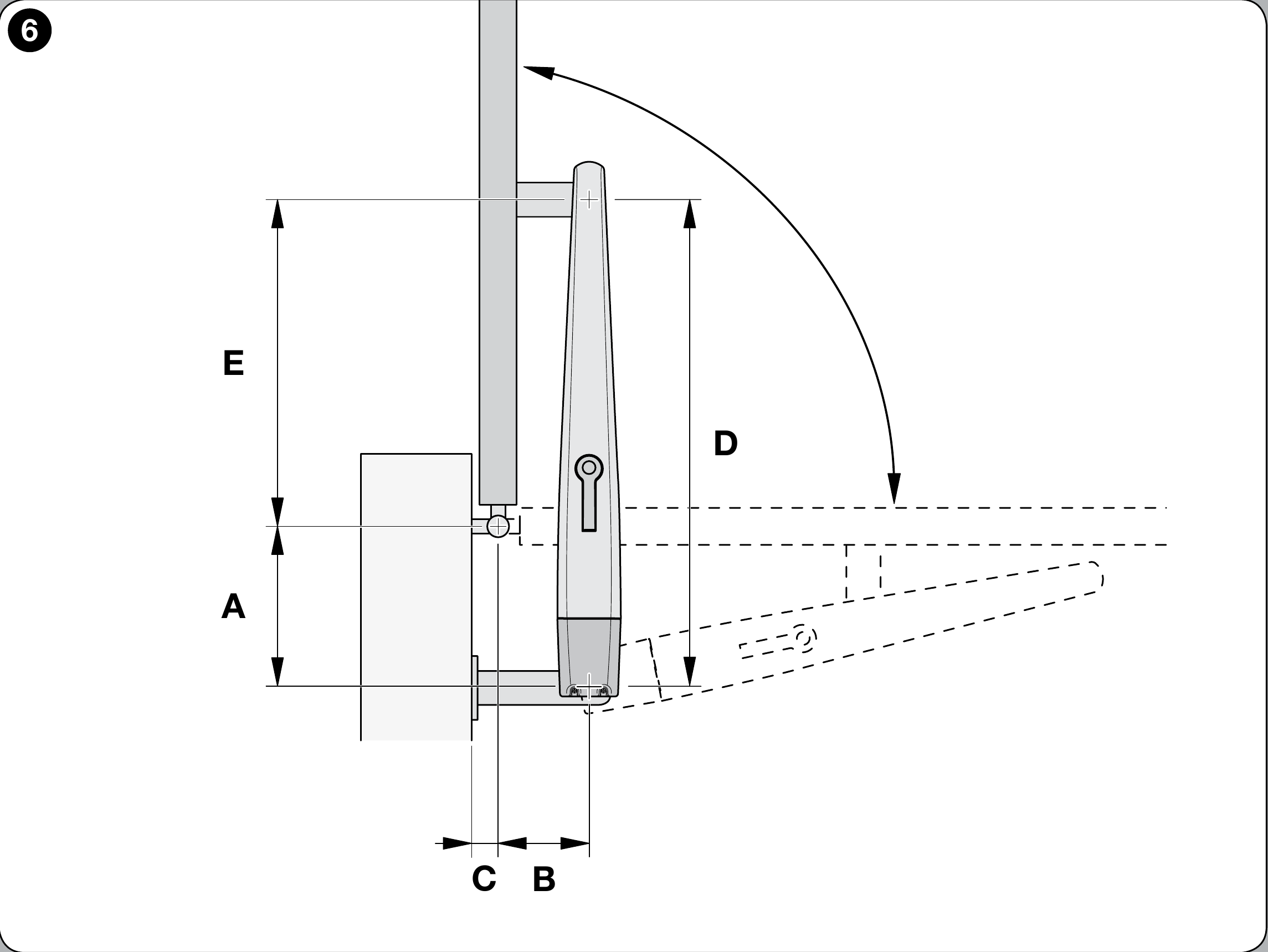
Before installation, check that the gate leaf is strong enough, moves smoothly by hand and allows access to the operator's manual release.
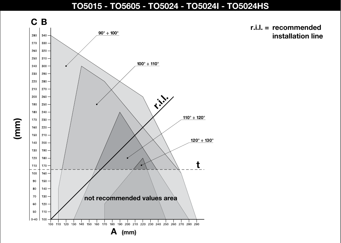
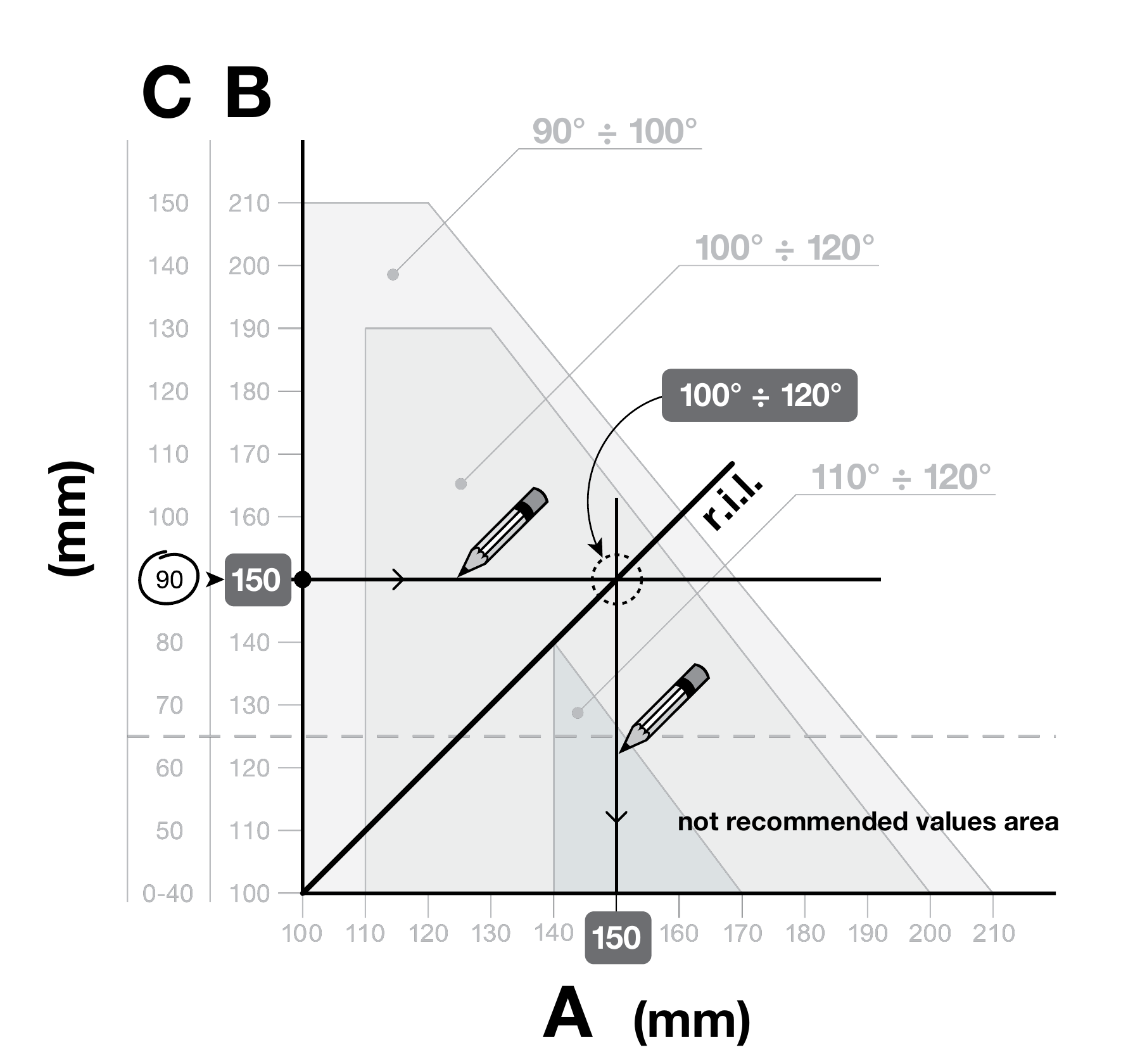
- Measure hinge offset C according to the gate drawing.
- On the graph, draw a horizontal line from C and read off B.
- The intersection with the recommended r.i.l. line indicates the permitted angle; read off A vertically.
- Before welding the bracket, check A, B and the full travel of the gate leaf. NICE does not recommend B values below line t.
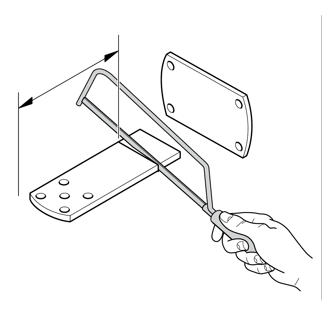
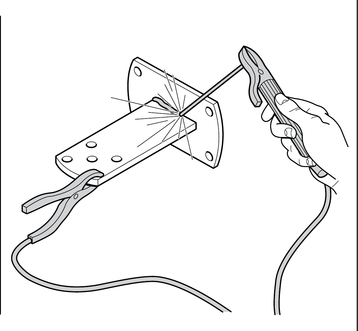
The supplied rear bracket for the Toona 4–5 series is 150 mm long. If its length needs to be adjusted, first check the geometry, then shorten it and firmly weld it to the mounting plate as shown in the NICE drawing.
II. Installing the front mounting bracket
Position the front bracket according to the fixed dimension D = 880 mm and the E table for the selected A value. The original NICE drawing for Toona 4–5 specifies a height difference of F = 34 mm. Before final installation, measure the brackets supplied and check that the gate leaf moves freely.
| A (mm) | E (mm) |
|---|---|
| 100 | 780 |
| 110 | 770 |
| 120 | 760 |
| 130 | 750 |
| 140 | 740 |
| 150 | 730 |
| 160 | 720 |
| 170 | 710 |
| 180 | 700 |
| 190 | 690 |
| 200 | 680 |
| 210 | 670 |
| 220 | 660 |
| 230 | 650 |
| 240 | 640 |
| 250 | 630 |
| 260 | 620 |
| 270 | 610 |
| 280 | 600 |
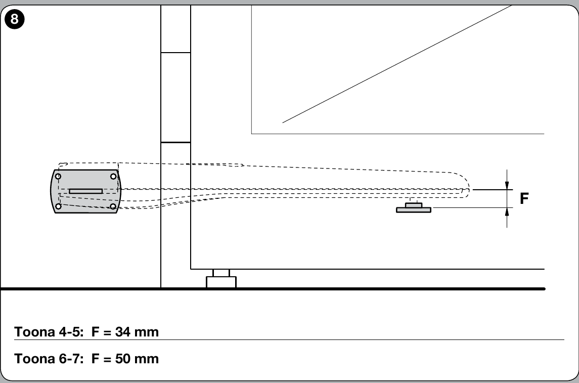
Secure the rear bracket to the fixed post and the front bracket to the rigid part of the gate leaf. Before final welding, check the full travel of the gate leaf and ensure the operator moves freely.
III. Installing the operator on the rear bracket
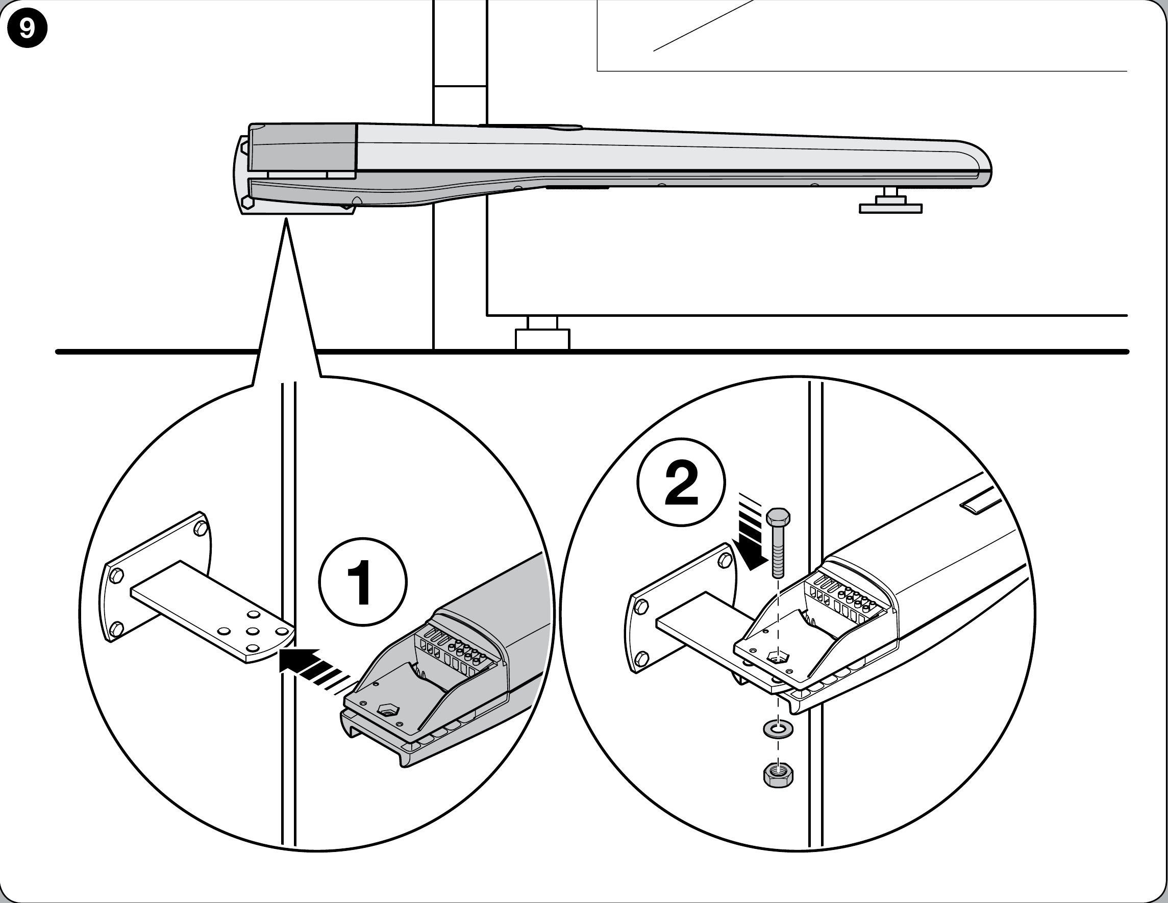
- Attach the motor to the rear bracket using the supplied pin or a bolt, washer and nut, as shown in the NICE drawing.
- Tighten the nut, then loosen it by approximately 1/10 of a turn to leave a small amount of play for the pivot to move.
IV. Installing the operator on the front bracket
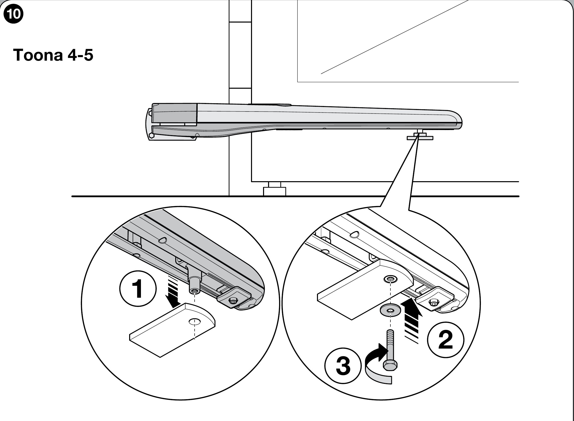
Temporarily attach the front bracket to the rigid part of the gate leaf, check its full travel, and only then complete the installation. Connect the motor to the bracket using the supplied pin and washer, as shown in the NICE drawing.
V. Adjusting the mechanical opening stop
The TO5024HS has an internal opening stop. When adjusting it, stay within the range marked in the NICE drawing as 100 mm max. Determine the closed position and whether external stops are needed based on the specific gate.
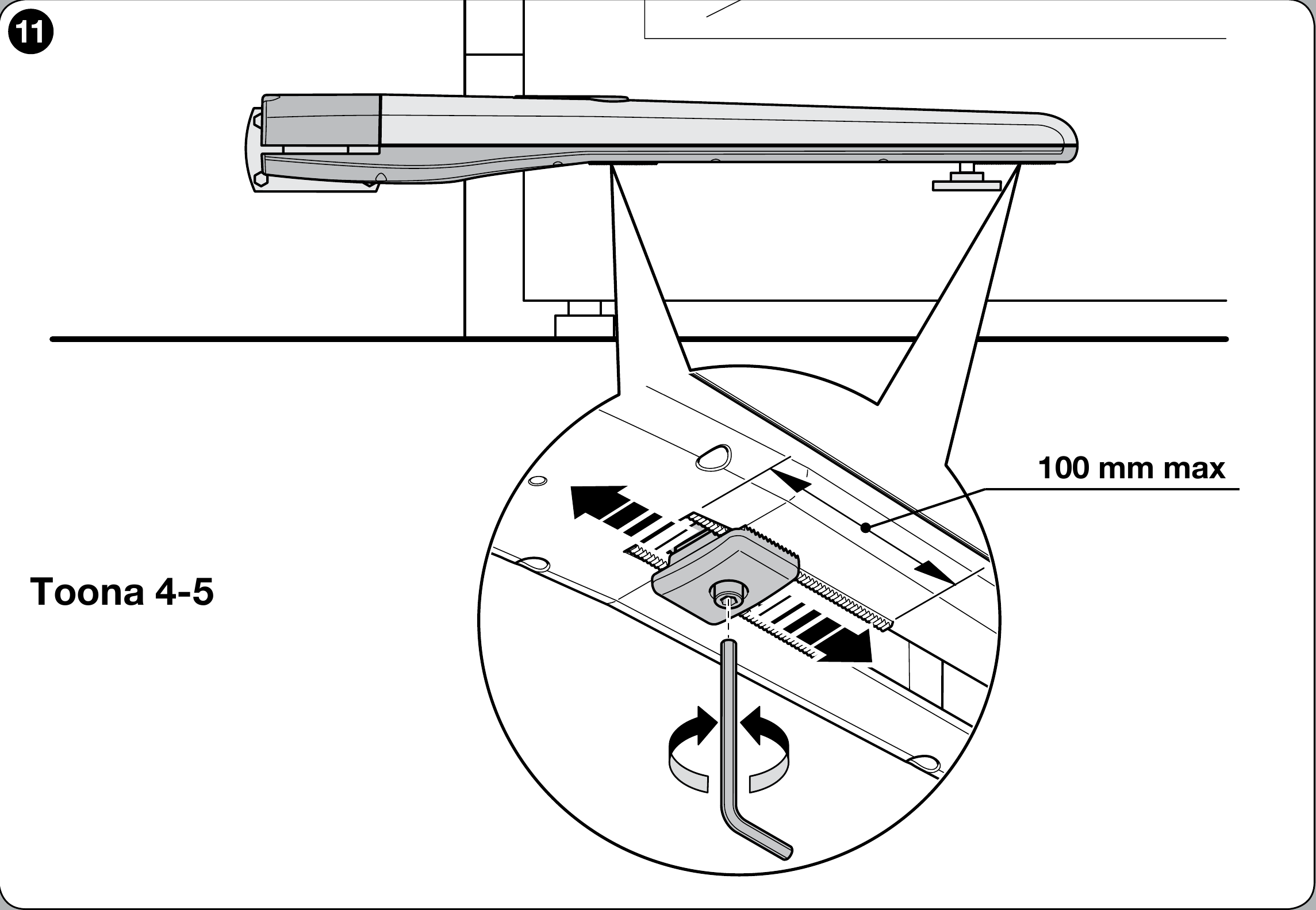
- Release the operator using the manual release procedure.
- Loosen the opening-stop screw and move the gate leaf by hand to the desired open position.
- Move the stop up against the pin and tighten the screw as shown in the drawing.
- Close the gate leaf by hand and re-engage the operator.
Motor wiring and connections
Disconnect the power supply before wiring. 24 V DC is the motor voltage; the control unit supply and accessory outputs must be considered separately. The motor has a separate pair of motor wires and a pair of encoder wires. For the 4–5 series operator, the terminals are labelled as shown in the illustration; for the 6–7 series, use its separate illustration. Determine the connection on the control board solely from the board actually installed in the system. For a gate that opens outwards, NICE specifies reversing the motor supply polarity; do not connect the encoder as the motor power supply.
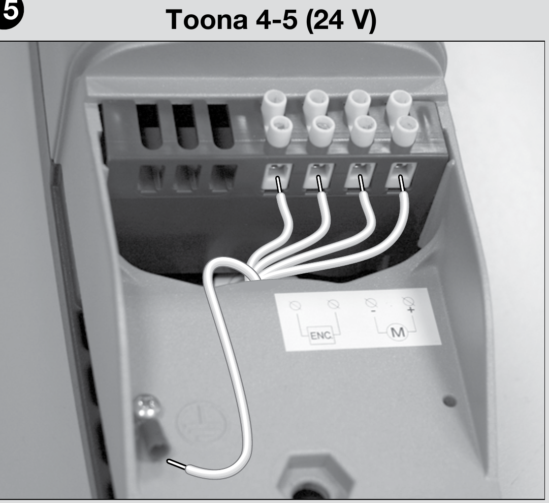
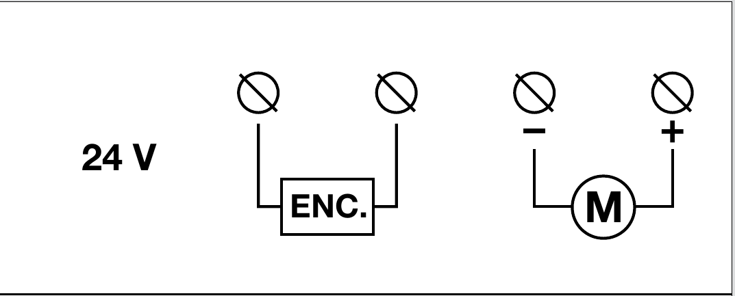
After wiring, check the direction of travel, stop positions and safety devices according to the manual for the control unit actually installed. Electrical connections and testing must be carried out by a qualified person.
Checks before first operation
Have a qualified technician install, electrically connect and commission the automated gate. Before switching on, the released gate leaf must move smoothly through its full travel without catching, and the brackets and post must remain secure.
- After wiring according to the control unit actually installed, check the direction of travel and set the positions as described in its instructions. Force settings are configured in the control unit, not in the motor itself.
- Test the opening stop, safety photocells, any safety edges, the STOP control and the manual release. The technician must verify the safety forces and, if there is a pedestrian gate in the gate leaf, that the operator is interlocked when it is open.
- Provide the customer with the release procedure and the manual for the control unit actually installed.
Connecting accessories to the MC824HR30
The following terminals belong to the MC824HR30/MCA1R30 control unit in a system with a TO5024HS motor, not to the motor itself. Disconnect the mains supply and backup battery before working. For a different control board, use its own wiring diagram.
| Accessories | Terminals, voltage and polarity |
|---|---|
| BlueBUS photocells | Connect compatible photocells, such as EPMB, using a two-wire connection to BlueBUS. + and − are interchangeable. Set the address and repeat the learning procedure after changing devices. |
| STOP and commands | Input STOP accepts a volt-free NO or NC contact, or a resistor element 8.2 kΩ; its status is learned. SbS, Open and Close accept a volt-free NO contact across the corresponding pair of terminals. Contacts have no +/− polarity; do not apply an external voltage to the input. |
| Auxiliary power supply | Right-hand terminal of the STOP pair = −; left-hand terminal of the SbS pair = +, with the image oriented as shown below (labels above the terminals). Power supply for a compatible reader or module: 24 V DC (−30% to +50%), 200 mA max., including in Stand-by mode. Wire the module's command relay separately as a volt-free contact; check the module's permitted voltage range and current consumption. |
| Flashing light, lock, indicator light | FLASH: 12 V DC, 21 W max.; ELS: 12 V AC, 15 VA max., no fixed +/− polarity; OGI: 24 V DC, 4 W max. For FLASH/OGI, the diagram does not specify the +/− order on the pair of terminals, so do not guess; for a polarized product, check the markings on both the control board and the product. Outputs may have different functions depending on programming. |
| Radio and backup power | The plug-in receiver goes into the SMconnector, and the backup battery goes into its own connector, according to the control board installed. They do not connect to BlueBUS or to the motor terminals. |
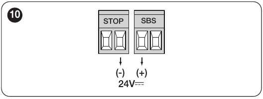
For detailed terminal locations, learning procedures and safety-device testing, see the MC824HR30 control unit's own manual.
Accessories by control unit
Choose accessories based on the interface of the control unit and receiver actually installed. Wireless and command devices may require additional equipment or configuration.
| What | Why | Type |
|---|---|---|
| Control unit | Controls a 24 V motor; procedures must correspond to the board actually installed. | |
| Receiver | Choose a radio receiver to match the transmitter's coding. | |
| Transmitter | Choose according to the receiver: two-way BD and LR modes require a compatible receiver. |
|
| Photocells | Use depends on the BlueBUS interface and, for wireless models, on additional equipment. | |
| Flashing light | The voltage and power rating must match the output of the control unit actually installed. |
Manual release of the drive
Release or engage the drive only when the gate leaf is stationary. If the gate has an electric lock, unlock it first. In the event of a fault, disconnect the power supply.
- Slide back the protective cover, insert the supplied key and turn it clockwise.
- Lift the release lever and move the gate leaf by hand.
- To re-engage the drive, lower the lever, turn the key counterclockwise, remove it and close the cover.
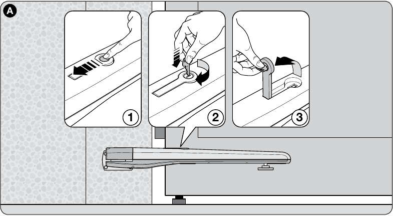
Before restarting, check that the drive is engaged and that no one is in the gate's path.
Inspection and maintenance
Service at least every 6 months must be carried out by a qualified technician. With the power disconnected, check the mounting, wear, corrosion and lubrication of the lead screw and nut. After switching on, test the movement, manual release and safety devices.
Technical specifications
Specification 75 cycles/hour applies according to NICE at nominal force. The 0.025 m/s speed is unloaded; under load, the manufacturer specifies 0.018 m/s.
| Parameter | Value |
|---|---|
Model | TO5024HS |
Drive motor | 24 V DC |
Maximum / nominal current draw | 5 A / 2.5 A |
Maximum / nominal power consumption | 120 W / 60 W |
Stroke | 505 mm |
Unloaded speed | 0.025 m/s |
Speed under load | 0.018 m/s |
Maximum / nominal force | 1,800 N / 600 N |
Cycles per hour at nominal force | 75 |
Protection | IP44 |
Operating temperature | −20 to +50 °C |
Insulation class | F |
Approximate service life according to NICE | 80,000 to 250,000 operating cycles |
Dimensions L × W × H | 965 × 115 × 105 mm |
Motor weight | 7.5 kg |
The motor weight shown in the table is the NICE figure excluding packaging. The weight for the variant being ordered also includes packaging and is used to calculate shipping costs.
Slovak-Czech NICE Toona installation manual. For programming, position learning, and radio settings, refer to the instructions for the control unit actually installed.
How can I order this item?
Choose the option that suits you:
- order online: use the buy button to add the goods to your shopping cart (you will find the buy button here in the product variants table).
- order by email: place your order at [email protected]