Manual for a track-mounted sliding gate
Technical guide · DIY construction · track sliding gate
This guide will help you prepare the space for a track sliding gate and choose the rail, wheels, guide system and drive. You’ll also find sample drawings for openings from 2.5 to 6.5 m. The drawings are provided as a planning aid.
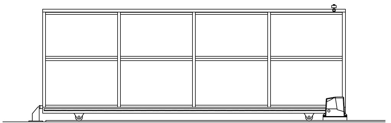
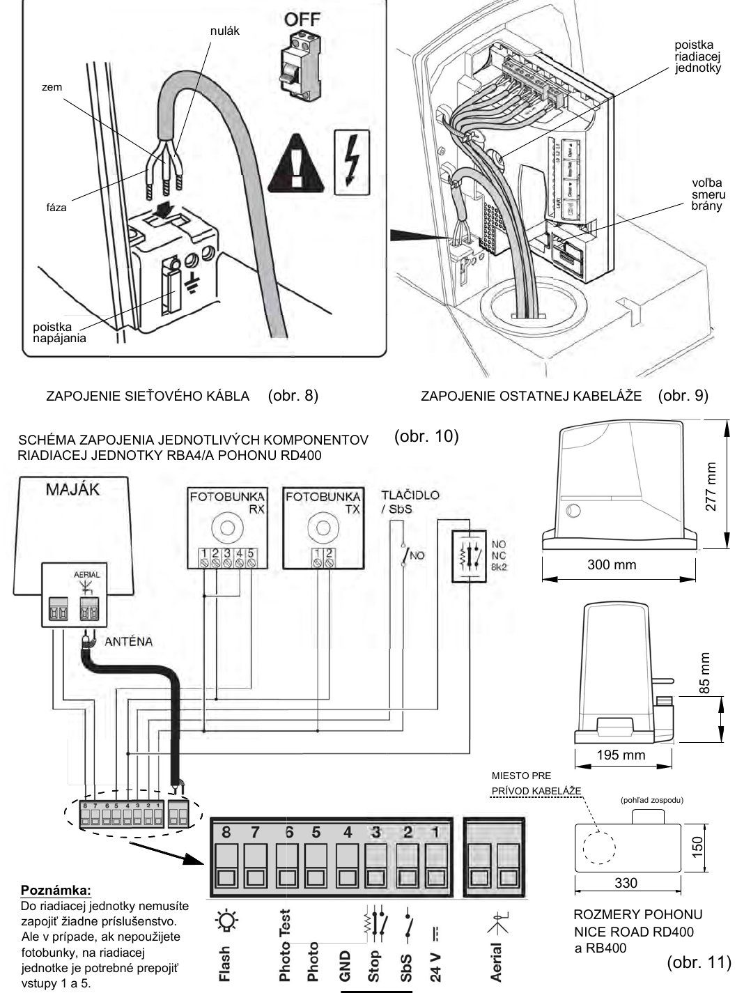
Image of a track sliding gate. Click to open a larger view.
Contents
- How a track gate works and its components
- Clearance, rail and concrete foundation
- Preparing the wiring and drive
- Drive wiring diagrams
- Choosing a rail for a track gate
- Choosing wheels for a track gate
- Choosing a guide system for a track gate
- Stops, locking and controls
- Checks before installing the drive
- Track gate drawings for openings from 2.5 to 6.5 m
- Component kits
From foundations to a complete track gate
A track gate carries its weight on the bottom wheels and travels along a rail laid along the entire gate path. When planning, first check that there is enough room for the gate to open, prepare a level base and wiring, then match the rail profile to the wheels, and finally choose the guide system, stops, locking hardware and, if required, a drive.
Main components of a track sliding gate
The gate leaf runs on a pair of bottom wheels. The wheels transfer the weight down to the rail and foundation. The top or side guide keeps the gate aligned laterally, but must not carry its weight.
| Running gear | U-shaped rail (U16 or U20) or V-shaped rail and compatible wheels fitted in the bottom frame channel. |
|---|---|
| Gate guide system | Top guide between rollers or side guide in a U/L profile. |
| End positions | Bottom and top stops that bring the gate to a halt and keep it stable. |
| Optional accessories | Hook lock, handles, grip handles, drives, rack sections, photocells, warning beacons and NICE remote controls (remotes from other brands). |
Clearance, rail and concrete foundation
The rail must be installed in a straight line, with no breaks between sections. The gate travels along it across the clear opening and continues into the space beside the fence. If the wheels are positioned at the ends of the frame, the rail must extend beneath the entire wheel path.
Rail / concrete foundation
Positioning the running gear and drive foundation.
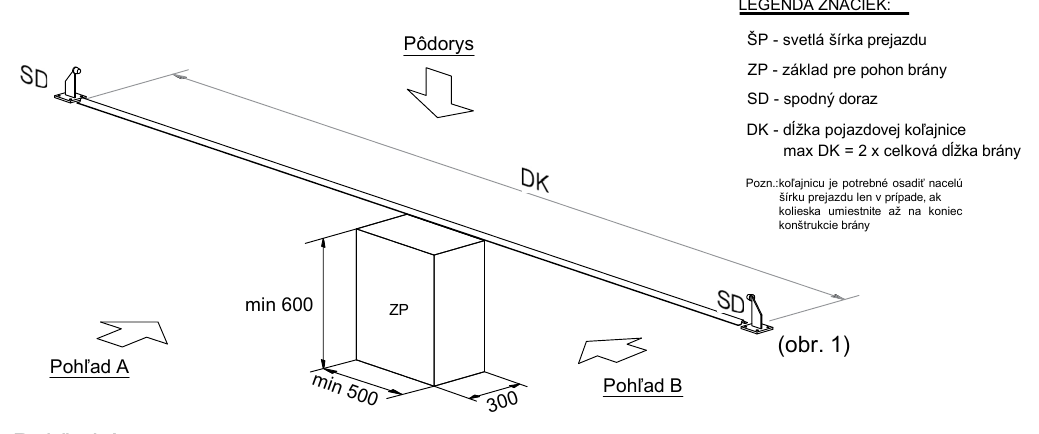
Front view, side view and plan showing the rail and drive foundation installation.
Key to the foundation diagram labels
| ŠP | Clear opening width. |
|---|---|
| DK | Running rail length. |
| SD | Bottom stop. |
| ZP | Gate drive foundation. |
The labels correspond to the diagrams above the key. Determine the exact dimensions and installation clearances from the current drawing for the product you have chosen.
Preparing the wiring and drive
Even if the gate will initially be operated manually, it’s a good idea to install conduit before pouring the concrete. You can then add a drive, photocells, a warning beacon or a key switch without cutting into the finished foundation.
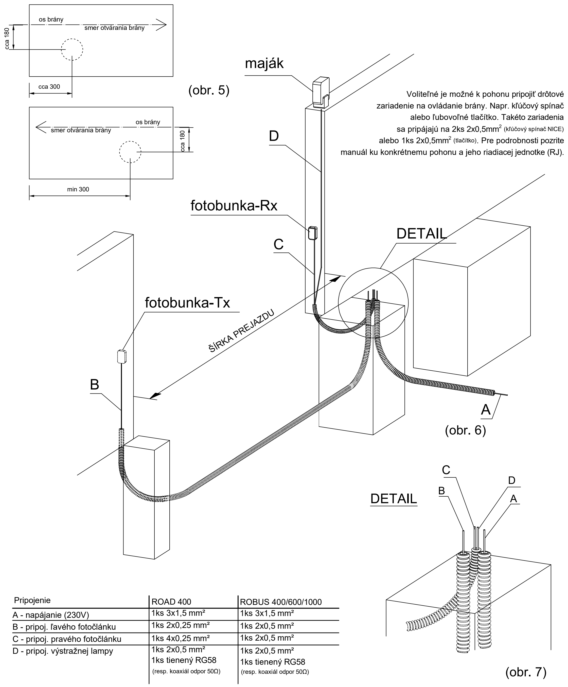
Wiring preparation, figures 5–7. Branch labels A–D correspond to the table below. Click to open a readable detail.
| Connection | NICE ROAD 400 | NICE ROBUS 400/600/1000 |
|---|---|---|
| A - 230 V power supply | 1 × 3 × 1.5 mm² | 1 × 3 × 1.5 mm² |
| B - left photocell | 1 × 2 × 0.25 mm² | 1 × 2 × 0.5 mm² |
| C - right photocell | 1 × 4 × 0.25 mm² | 1 × 2 × 0.5 mm² |
| D - warning beacon | 1 × 2 × 0.5 mm² + thin RG58, 50 Ω coaxial cable | 1 × 2 × 0.5 mm² + thin RG58, 50 Ω coaxial cable |
For power cable lengths over 30 m, NICE specifies a conductor cross-section greater than 3 × 1.5 mm² for the ROBUS RB400/RB600/RB1000 drives.
Optional rail heating: A resistance heating cable can be installed inside the rail. Since the gate area usually has a drive and a 230 V supply, the heating can be controlled by a temperature or humidity sensor, or by a simple switch.
Drive wiring diagrams
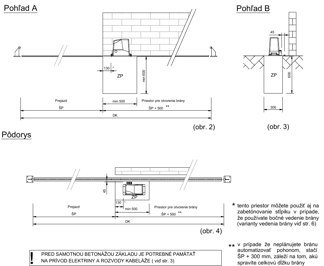
Choose the diagram according to the drive and control unit model. The older NICE Robus RB and newer NICE Robus RBS have different terminal blocks. Their wiring diagrams are not interchangeable. Always refer to the manual for the specific control unit.
NICE Robus RB400 / RB600 / RB1000
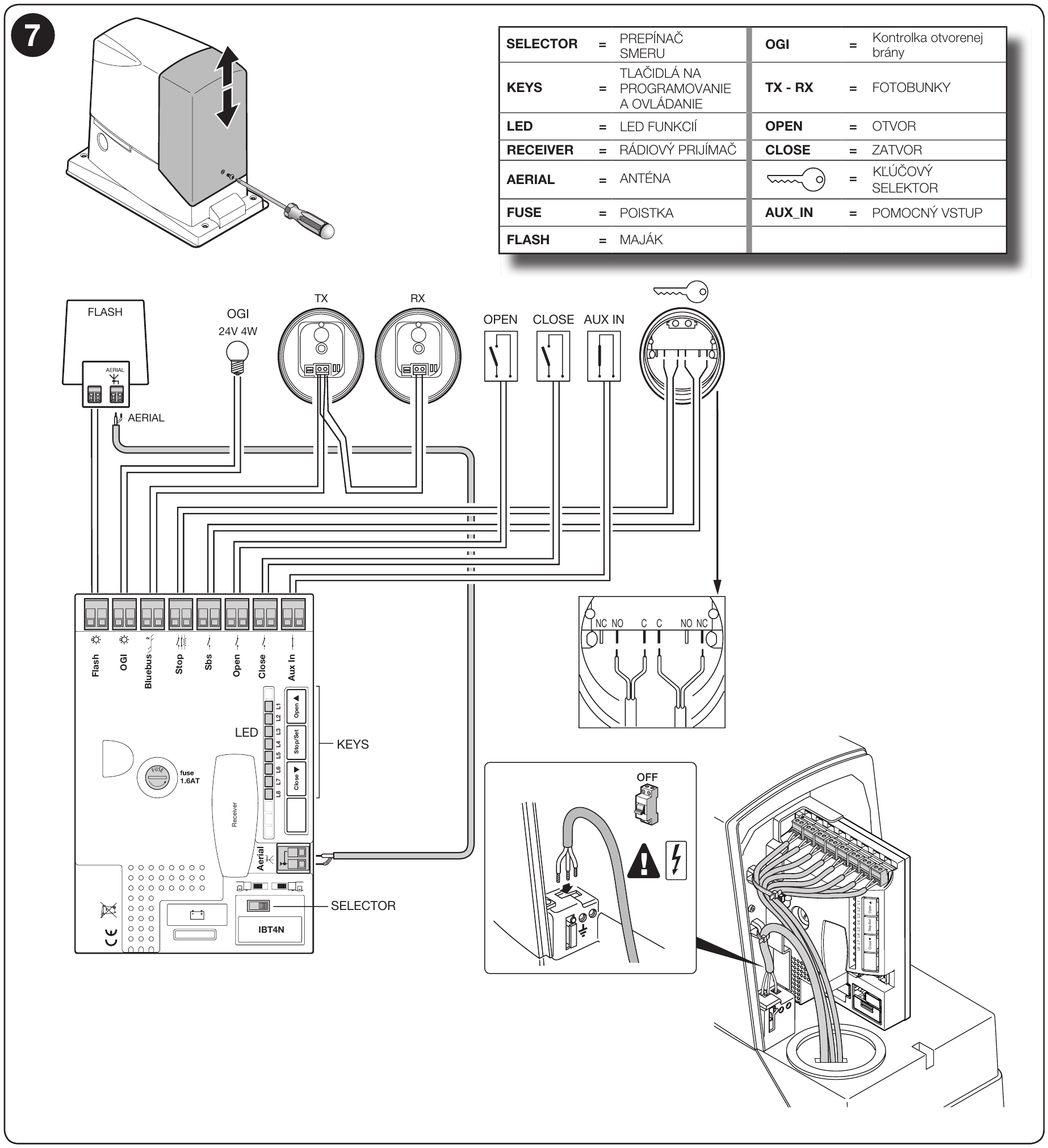
Diagram from the NICE ROBUS400/600/1000 installation manual, printed page 11, figure 7. Click to open a readable detail.
NICE ROBUS400/600/1000 installation manual – wiring diagram (PDF, page 12 of the file).
NICE Robus RB600 – product and installation manual. For other control unit versions, use the documentation for that specific version.
NICE Robus RBS400 / RBS600
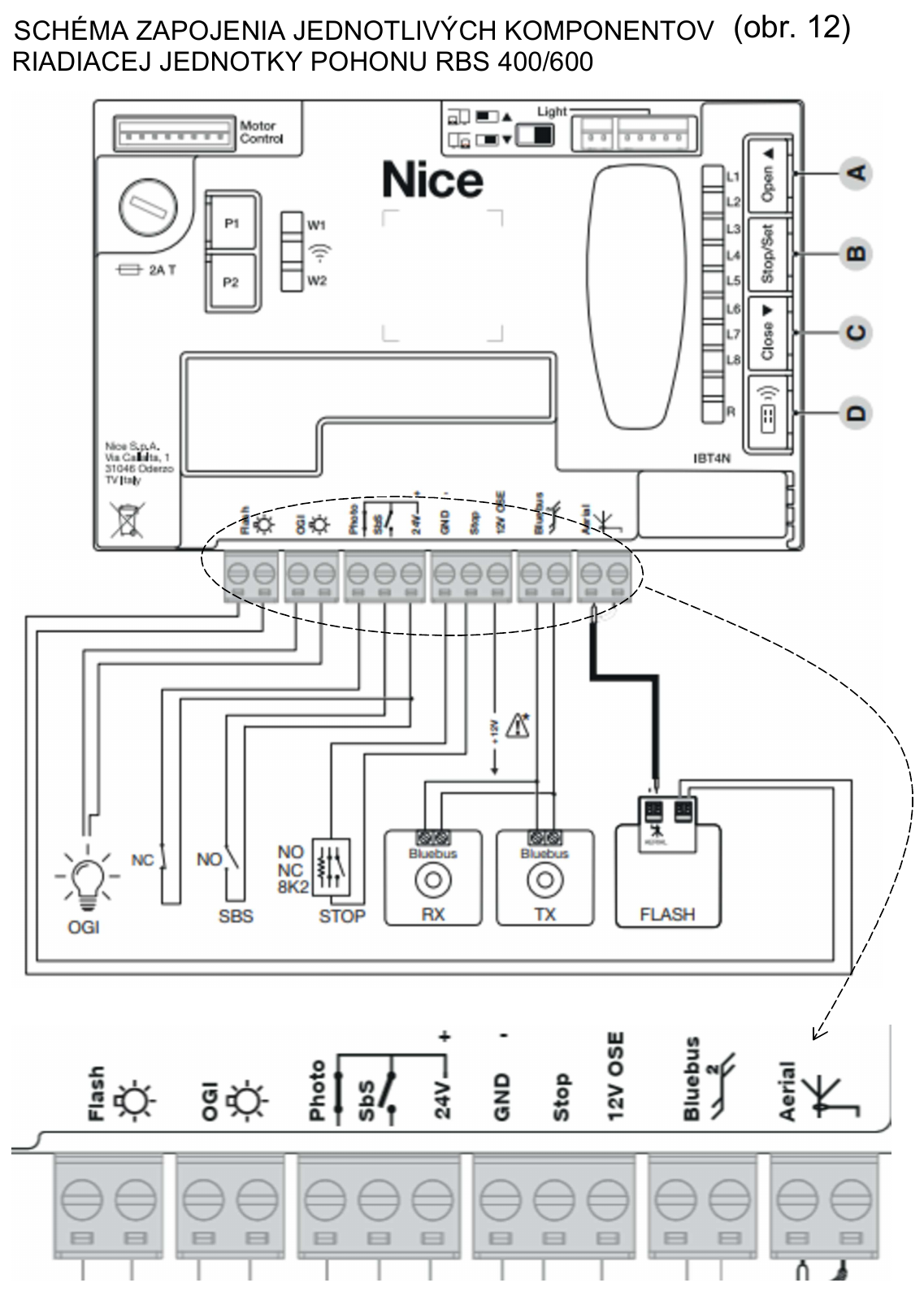
Wiring diagram for the individual components of the RBS400/600 control unit, Figure 12. Click to open the diagram and terminal block detail in full resolution.
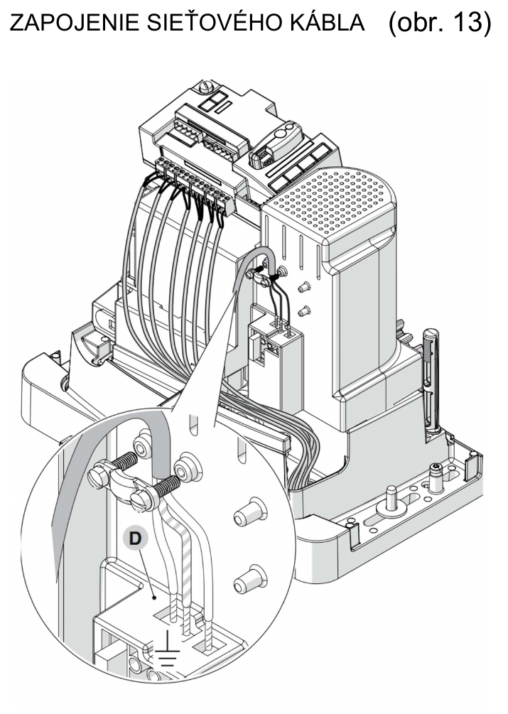
Mains cable wiring, Figure 13. Click to open a readable detail.
The original is also available for the older ROAD setup: original NICE ROAD 400 diagram. Current range: NICE sliding gate operators.
Choosing a track for a tracked gate
First choose the track profile, then the rollers. The U-track has a rounded running surface for a U-groove roller, while the V-track has a 90° apex and takes a V-groove roller. Tracks for bolting down are fixed to a level, fully cured base; the cast-in version is installed during concreting.
| Track | Profile | Installation | Material |
|---|---|---|---|
| U16 track for bolting down | U16 | for bolting down | Zn |
| U20 track for bolting down | U20 | for bolting down | Zn |
| V-track for bolting down | V | for bolting down | Zn |
| U20 track for casting into concrete | U20 | for casting into concrete | Zn |
| INOX U16 track for bolting down | U16 | for bolting down | INOX |
| INOX U20 track for bolting down | U20 | for bolting down | INOX |
| INOX V-track for bolting down | V | for bolting down | INOX |
The table covers standard U/V tracks. Curved tracks are intentionally omitted. The full current range is in the category tracks for tracked sliding gates.
Choosing rollers for a tracked gate
Once you have chosen a compatible track profile, consider the gate weight, roller diameter and mounting method. A gate usually uses one pair of rollers, so the load capacity on product pages is stated per pair for standard models.
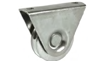
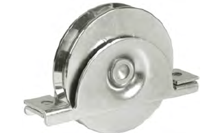
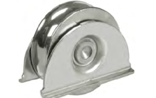
- Roller with bracket is the most commonly used option and is easier to install.
- Recessed roller is used when you want to reduce the clearance between the gate and the ground. It is recessed into the structure’s bottom profile.
- Recessed roller Depending on the type, it can be bolted or welded to the structure.
| Product | Track | Available diameters |
|---|---|---|
| IBFM roller with bracket for bolting down | U16 | Ø50, Ø60, Ø80, Ø90, Ø100 |
| IBFM recessed roller for bolting down | U16 | Ø60, Ø80, Ø90, Ø100 |
| IBFM recessed roller for welding | U16 | Ø60, Ø80, Ø90, Ø100 |
| IBFM roller with bracket for bolting down | U20 | Ø80, Ø100 |
| IBFM recessed roller for bolting down | U20 | Ø80, Ø100, Ø140 |
| IBFM roller with bracket for bolting down | V | Ø50, Ø60, Ø80, Ø90, Ø100 |
| IBFM recessed roller for bolting down | V | Ø60, Ø80, Ø90, Ø100 |
| IBFM recessed roller for welding | V | Ø80, Ø90, Ø100 |
Choose the diameter from the options table on the relevant product page.All rollers for tracked gates
Choosing a guide for a tracked gate
The guide keeps the top of the gate on track. It does not carry the weight of the gate leaf, and the rollers must not clamp the frame so tightly that the gate binds.
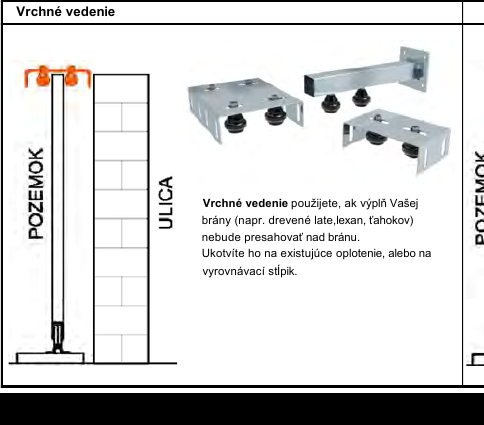
View top guide
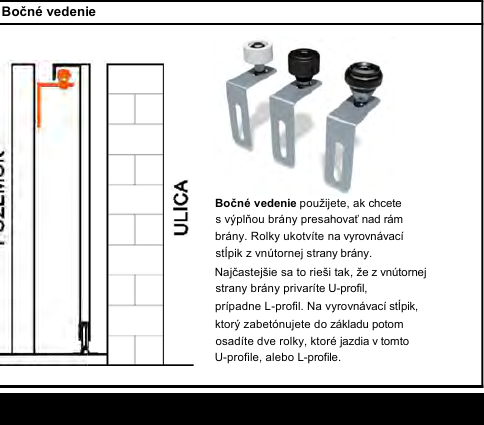
View side guide
| Top guide | Side guide |
|---|---|
| Use this if the infill does not extend above the frame’s top profile. The roller bracket is fixed to a fence, wall or alignment post. | Use when the infill is to extend above the frame. A U- or L-profile is welded to the inside of the gate leaf, and the roller from the post runs in it. |
Choose the guide system to suit the gate frame and infill.All guides for track gates
Stops, locking and controls
Gate stops
The bottom stop halts the frame when the gate opens or closes. The top stop also stabilises the gate leaf in its end position. The gate operator stops the gate at the set end positions. Keep the mechanical stops in place too; they will catch the gate when it is moved manually after the operator has been disengaged.
See bottom and top stops for track gates.
Manual locking
A hook lock is used for a manually operated gate. For a track gate, you also need a pin or another catch to prevent the gate leaf from lifting out of the lock. Choose a compatible handle or pull handle to suit the thickness of the frame and infill.
See locks, handles and pull handles for track gates.
Operating the gate operator
The gate can be operated with a NICE remote control or a remote control from another brand, key switch, push button, keypad, reader or smart module. Check receiver and remote-control compatibility against the specific control unit, not just the operator brand.
Checks before installing the gate operator
Before installing the operator, move the gate manually through its full travel. Movement must be smooth, without catching or excessive resistance. Check the guide system and stops. The operator must not be used to compensate for faulty mechanical installation.
Track gate drawings for clear opening widths of 2.5 to 6.5 m
Click the image to open the drawing. Basic dimensions, profiles and weights are also listed in the text below.
These values do not represent a universal load capacity for every gate with the same clear opening width.
Track gate with a 2.5 m clear opening width
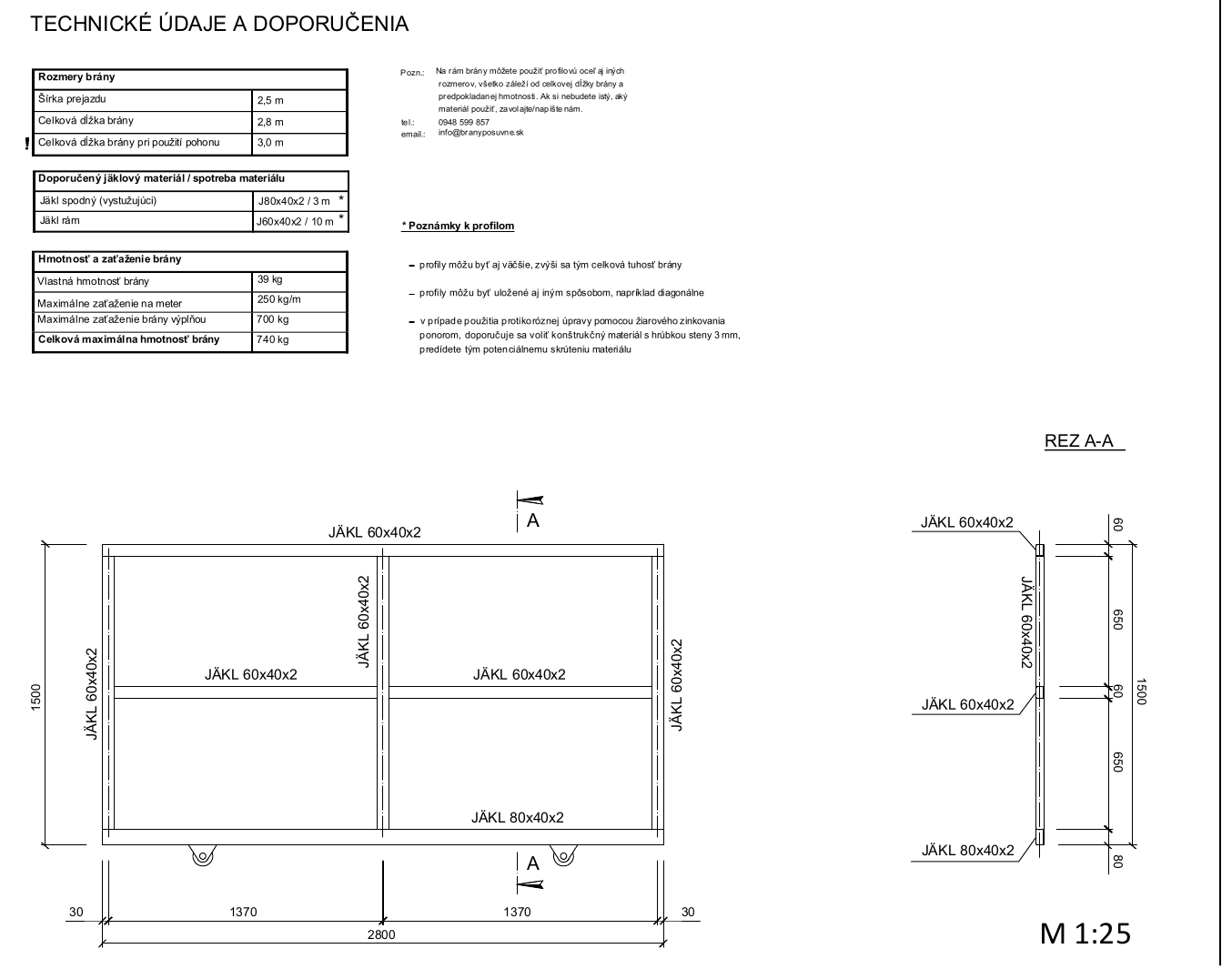
Click to open the complete drawing at full resolution.
- Overall gate length 2.8 m
- With operator 3.0 m
- Bottom profile J80 × 40 × 2 / 3 m
- Frame J60 × 40 × 2 / 10 m
- Self-weight 39 kg
- Max. load per metre 250 kg/m
- Max. infill weight 700 kg
- Max. total weight 740 kg
Track gate with a 3.0 m clear opening width
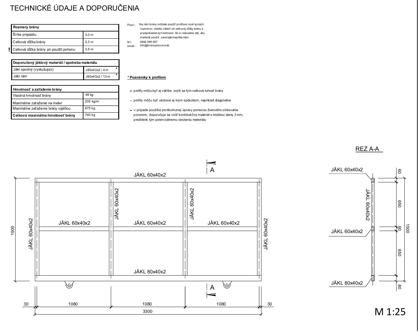
Click to open the complete drawing at full resolution.
- Overall gate length 3.3 m
- With operator 3.5 m
- Bottom profile J80 × 40 × 2 / 4 m
- Frame J60 × 40 × 2 / 13 m
- Self-weight 48 kg
- Max. load per metre 205 kg/m
- Max. infill weight 675 kg
- Max. total weight 740 kg
Track gate with a 3.5 m clear opening width
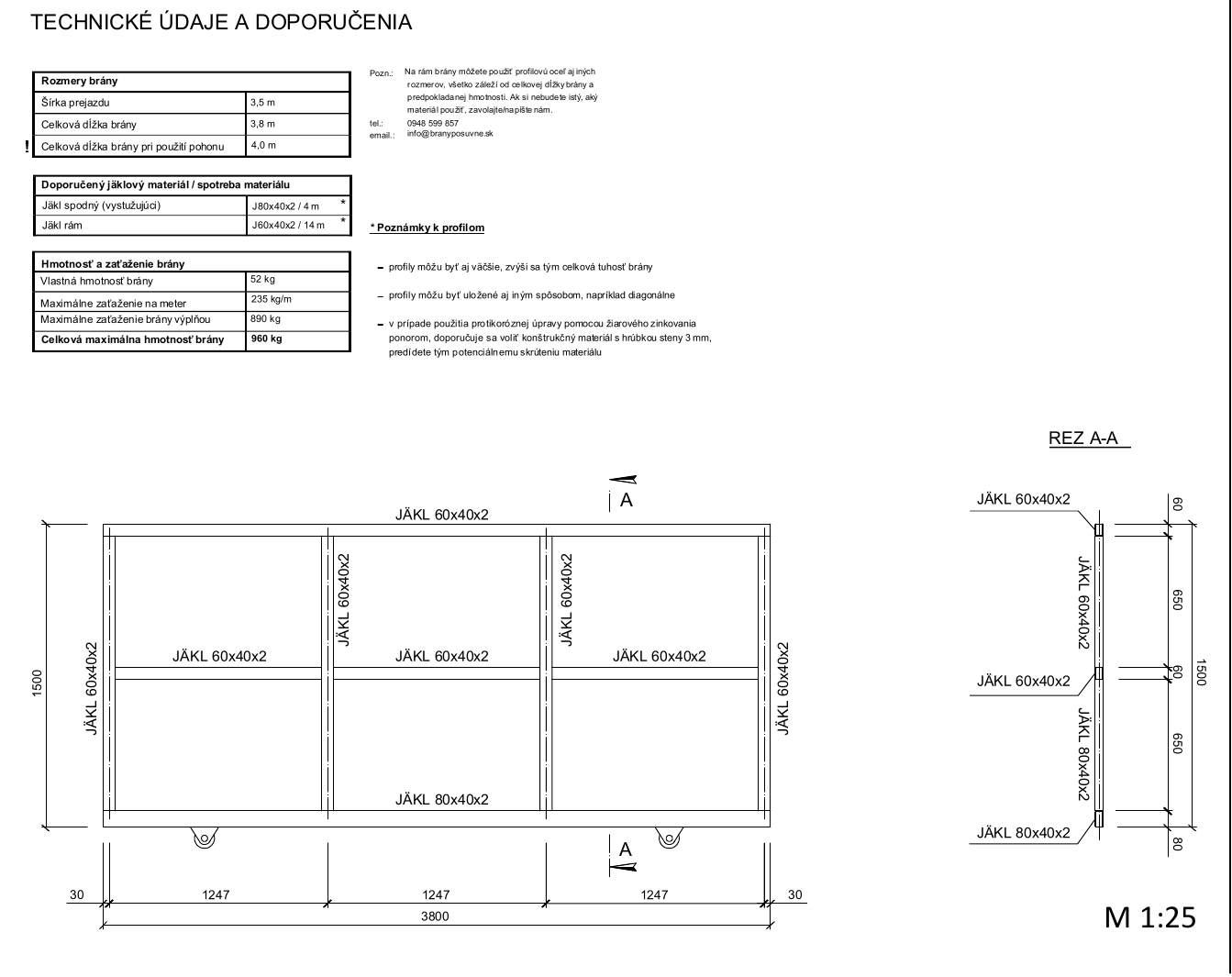
Click to open the complete drawing at full resolution.
- Overall gate length 3.8 m
- With operator 4.0 m
- Bottom profile J80 × 40 × 2 / 4 m
- Frame J60 × 40 × 2 / 14 m
- Self-weight 52 kg
- Max. load per metre 235 kg/m
- Max. infill weight 880 kg
- Max. total weight 960 kg
Track gate with a 4.0 m clear opening width
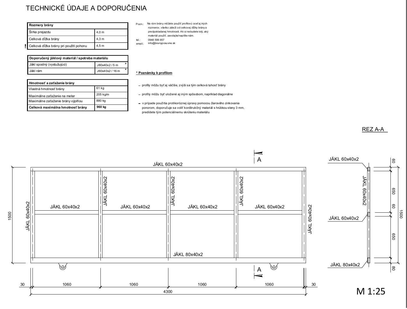
Click to open the complete drawing at full resolution.
- Overall gate length 4.3 m
- With operator 4.5 m
- Bottom profile J80 × 40 × 2 / 5 m
- Frame J60 × 40 × 2 / 16 m
- Self-weight 61 kg
- Max. load per metre 205 kg/m
- Max. infill weight 880 kg
- Max. total weight 960 kg
Track gate with a 4.5 m clear opening width
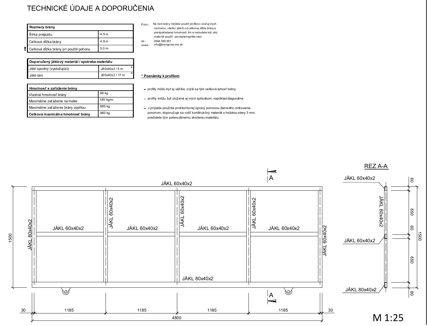
Click to open the complete drawing at full resolution.
- Overall gate length 4.8 m
- With operator 5.0 m
- Bottom profile J80 × 40 × 2 / 5 m
- Frame J60 × 40 × 2 / 17 m
- Self-weight 66 kg
- Max. load per metre 185 kg/m
- Max. infill weight 885 kg
- Max. total weight 960 kg
Rail sliding gate with a clear passage width of 5.0 m
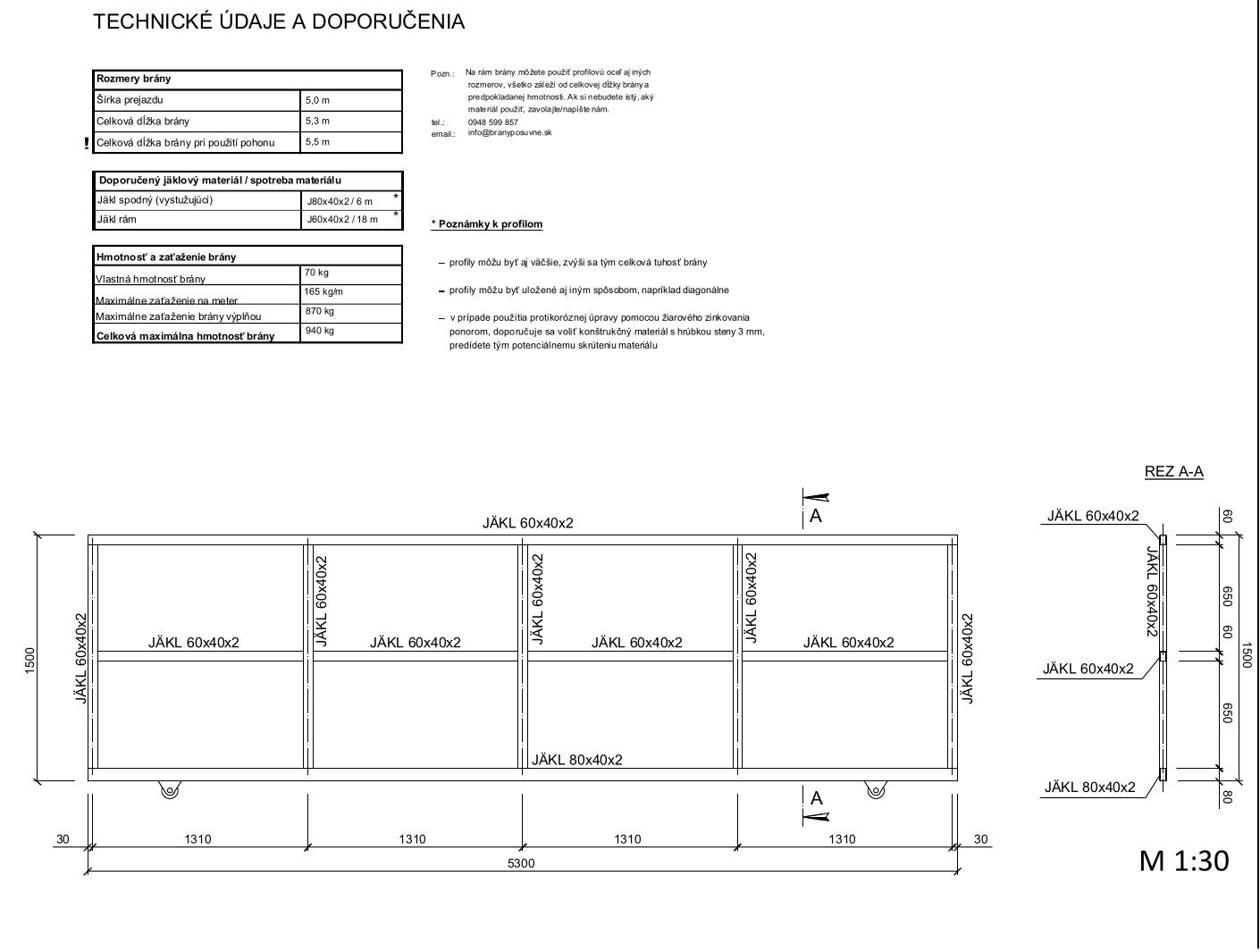
Click to open the complete drawing in full resolution.
- Overall gate length 5.3 m
- With drive 5.5 m
- Bottom profile J80 × 40 × 2 / 6 m
- Frame J60 × 40 × 2 / 18 m
- Self-weight 70 kg
- Max. load per metre 165 kg/m
- Max. infill weight 870 kg
- Max. total weight 940 kg
Rail sliding gate with a clear passage width of 5.5 m
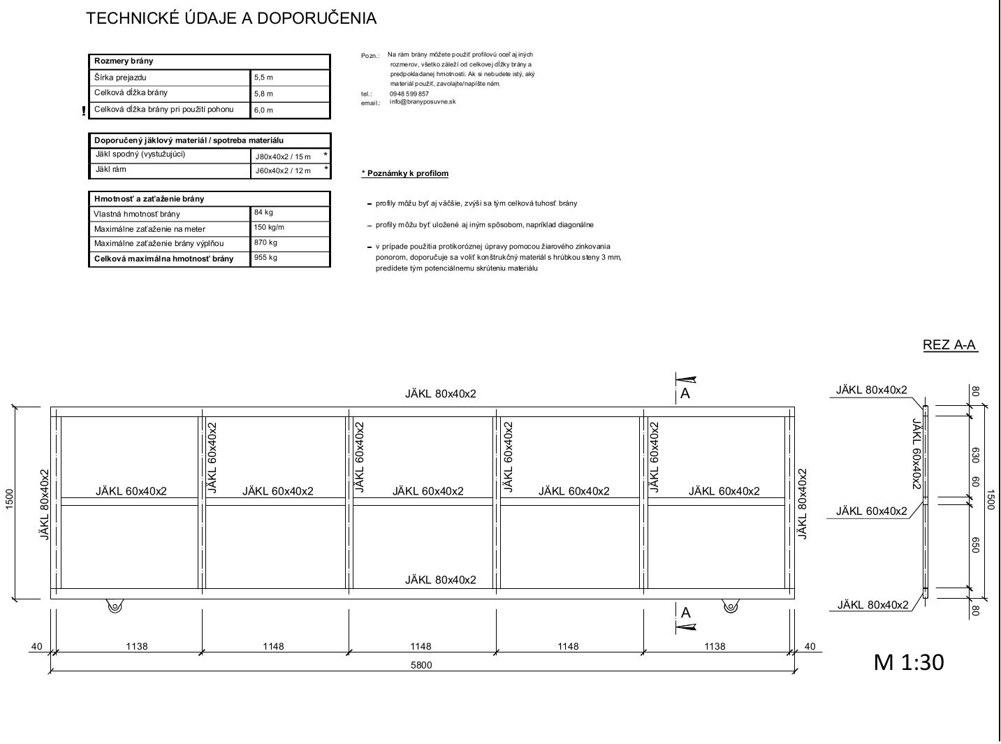
Click to open the complete drawing in full resolution.
- Overall gate length 5.8 m
- With drive 6.0 m
- J80 × 40 × 2 profiles 15 m
- J60 × 40 × 2 profiles 12 m
- Self-weight 84 kg
- Max. load per metre 150 kg/m
- Max. infill weight 870 kg
- Max. total weight 955 kg
Rail sliding gate with a clear passage width of 6.0 m
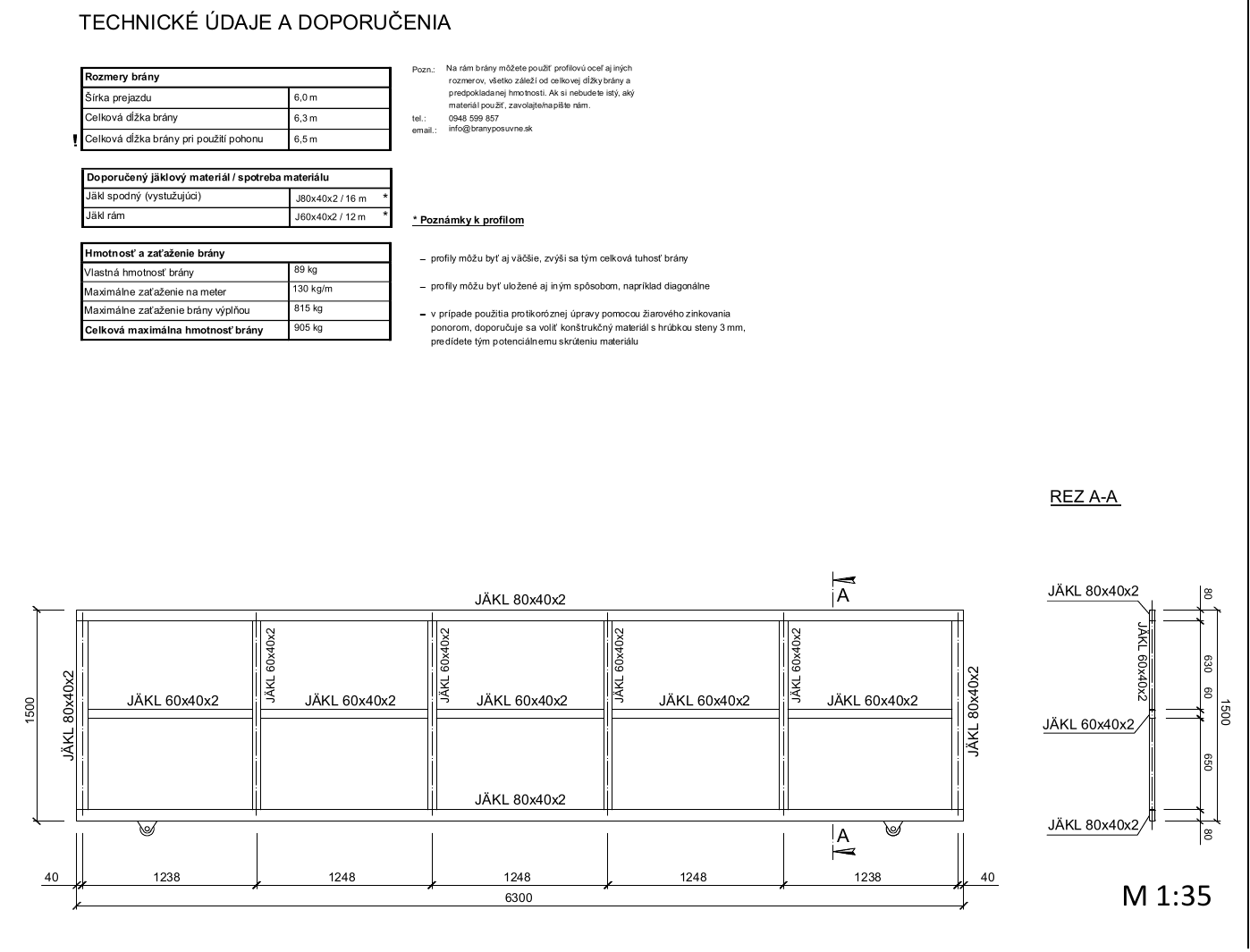
Click to open the complete drawing in full resolution.
- Overall gate length 6.3 m
- With drive 6.5 m
- J80 × 40 × 2 profiles 16 m
- J60 × 40 × 2 profiles 12 m
- Self-weight 89 kg
- Max. load per metre 130 kg/m
- Max. infill weight 815 kg
- Max. total weight 905 kg
Rail sliding gate with a clear passage width of 6.5 m
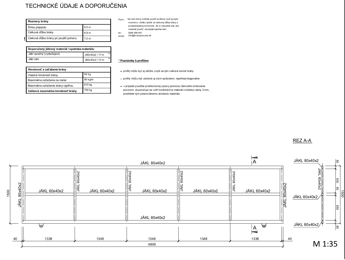
Click to open the complete drawing in full resolution.
- Overall gate length 6.8 m
- With drive 7.0 m
- J80 × 40 × 2 profiles 17 m
- J60 × 40 × 2 profiles 13 m
- Self-weight 94 kg
- Max. load per metre 90 kg/m
- Max. infill weight 610 kg
- Max. total weight 700 kg
The dimensions shown are examples. Profiles may be larger or arranged diagonally. For hot-dip galvanising, material with a 3 mm wall thickness is recommended to reduce the risk of the frame twisting.
The weight and load values do not constitute a structural assessment of a specific gate. For a heavy, solid infill, an exposed location, an unusual height or a non-standard size, have the frame, wheels, track, anchors and drive checked.
Choosing a component kit made easy
A ready-made kit combines the track, wheels, stops and guide, selected to match the passage width. Choose according to the passage width, finish and whether you want the kit to include a drive.
Standard refers to kits with metal components protected by galvanising. INOX refers to stainless-steel metal components. Non-metal parts, such as nylon rollers, vary depending on the specific kit. For kits with a drive, its type is listed directly in the table.
| Kit / passage width | Finish | Drive included |
|---|---|---|
| Kit up to 3.0 m | Standard | No drive |
| Kit up to 4.5 m | Standard | No drive |
| Kit up to 6.5 m | Standard | No drive |
| Kit up to 3.0 m | Standard | NICE Road 400 |
| Kit up to 4.5 m | Standard | NICE Robus RBS400 |
| Kit up to 6.5 m | Standard | NICE Robus RBS600 |
| Kit up to 3.0 m | Stainless steel | Without operator |
| Kit up to 4.5 m | Stainless steel | Without operator |
| Kit up to 6.5 m | Stainless steel | Without operator |
Choose the type of rollers and guide on the product page according to the installation method and gate infill. Always check the exact contents, available options, price and stock status for the specific kit.
Full current range: track gate kits.
Couldn't find the answer? Call us
If you couldn't find the information you were looking for, contact us. We can help you choose components for your specific track gate.
Information we need to recommend suitable products
- the clear opening width and the total space available for opening,
- the dimensions of the entire gate leaf and its estimated weight including infill,
- whether the track should be bolted down or set in concrete,
- a photo or sketch of the site and information about the type of surface,
- whether the gate will be manual or powered.
Prepared by Eng. Ján Kubíček.
Last updated: 16. 9. 2026.