A stop defines the end position, a drop bolt secures the gate leaf, and a suitable lock locks it. Choose them to suit the frame, finished driveway surface, and operating method. On an automated gate, the securing mechanism must work with the operator; release a standard manual drop bolt before starting the operator.
| Swing gate: choose a topic | |
|---|---|
| Measuring and procedure | |
| Space and slope | Frame, hinges, and infill |
| Operator and brackets | Stops and accessories |
Check the complete assembly before ordering
| You choose | What you need with it |
|---|---|
| Manual drop bolt | Matching keep or sleeve, frame fixing, and the required bolt reach. If the sleeve has no stop face, a separate stop must define the gate leaf position. |
| Lock | Keep, suitable mounting position, and access to the key. For electric locking you also need the correct power supply, controls, and emergency release. |
| Operator kit | Check the number of motors, the specific control unit, and the package contents. Brackets, receiver, transmitters, photocells, and warning light may vary between kits. Check separately extended brackets, stops, cables, and anchors. |
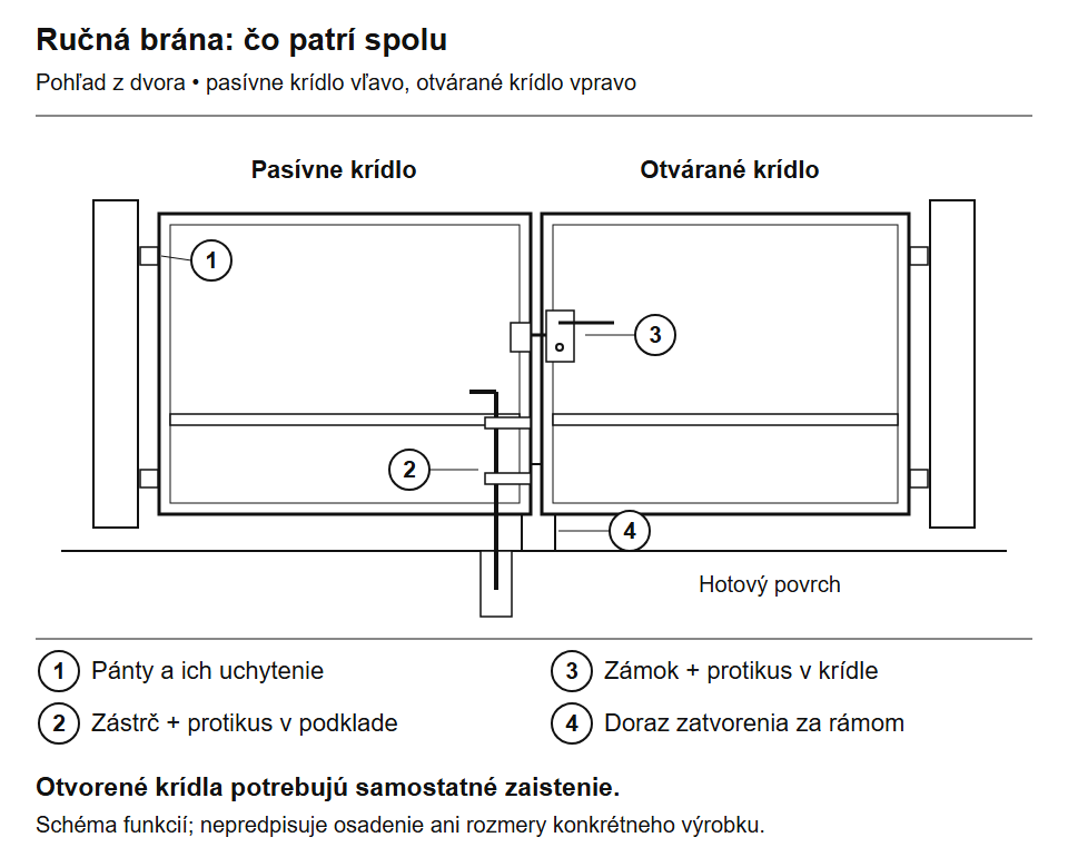
Principle of a manual assembly, viewed from the yard. Hinges and infill are sized separately; open gate leaves need their own securing mechanism. Click to enlarge.
What stops the gate and what keeps it in place
| What | Why | Type and selection |
|---|---|---|
| Closing stop | Defines the final position of the closed gate leaves. | Bottom stop Choose according to the frame height above the finished surface and the fixing method. |
| Opening stop | Stops the gate leaf at the end of its opening travel. | External or built-in mechanical stop, depending on the specific operator. Check the position and opening angle. |
| Open-leaf catch | It also holds a manual gate leaf so it cannot swing back freely. | Choose the catch and how it is released. A fixed stop alone does not guarantee this function. |
| Drop bolt | Secures, for example, the inactive leaf of a manual gate. | Bolt and suitable keep; compare the diameter, travel, and mounting height. |
| Lock | Locks the gate. | Manual locking or electric locking depending on how the gate is operated. |
When automating the gate, select stops according to the operator manual. A learned operating time is not a universal substitute for a mechanical stop. A fixed open-leaf catch must not remain engaged when the motor starts closing the gate.
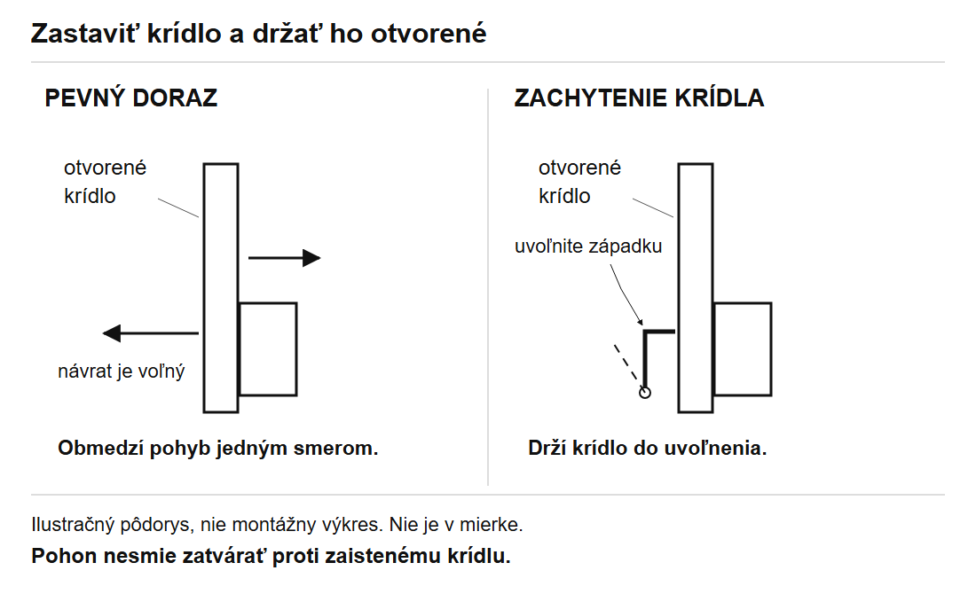
Install the stop in relation to the finished paving
Before drilling, check contact with the frame, clearance beneath the vehicle, and the travel path of both gate leaves. Paving installed later can change both the gap below the frame and the required drop-bolt reach. Choose fixings suitable for the load-bearing substrate; the thin paving slab alone may not be sufficient.
For a low-clearance car, also check that it can pass over the stop. Make sure gravel, leaves, and snow can be cleared from the drop bolt and its socket. Keep the water drain clear; a drainage hole alone does not guarantee protection against freezing.
Example: finished paving and a low-clearance car
You are selecting a central stop and a bottom drop bolt. The height of the frame's lower edge, the vehicle's path, and the load-bearing substrate beneath the paving all matter.
- Close and align the gate leaves. Measure the gap between the finished surface and the frame at the stop location, and the position the drop-bolt pin will reach.
- Compare the stop height with its contact point on the frame and the vehicle's actual clearance. Where the slope changes, the vehicle's published ground clearance is not enough.
- If you choose a recessed EGS sleeve, use a separate stop to define the end position. With SABO, assess the stop face, bolt hole, anchoring, and cleaning access together.
Related parts and procedures: stops, EGS and SABO, choosing a drop bolt.
How to choose a drop bolt with a suitable keep
On a manual double-leaf gate, the inactive leaf is often secured with a bottom drop bolt. Choose one only after determining the position of the closed frame and the finished surface height.
- Measure the reach: the distance between the drop-bolt fixing point and the keep. Compare both the overall length and the usable travel of the product.
- Compare the bolt and the hole: their diameters, positions, and required insertion depth, as shown in the product drawing.
- Check operation: allow space for the handle and its movement, and make sure the raised bolt stays secured and does not scrape the ground when the gate opens.
- Choose the keep: a recessed sleeve or a stop with a hole. Determine how it will be anchored and drained, and how it can be accessed for cleaning.
| Stops and drop bolts | |
|---|---|
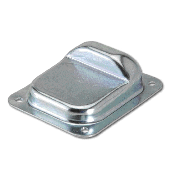 |
For precisely defining the closed position. Installation is adapted to the substrate and the location in the driveway. |
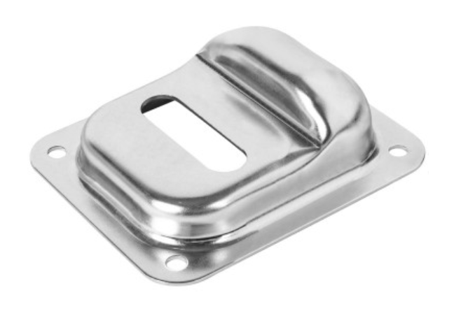 |
In a manual assembly, it can work with a drop bolt; choose a matching size for the hole and bolt. |
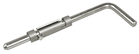 |
Screw-on drop bolt for securing a gate leaf into the ground; choose the length and keep. |
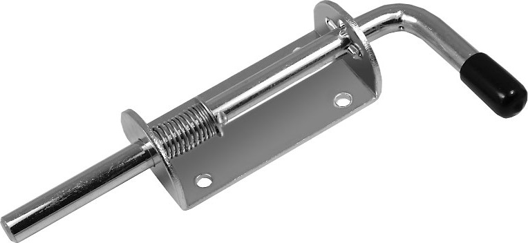 |
Spring-loaded version for manual operation. Check the locking method and installation against the specific product. |
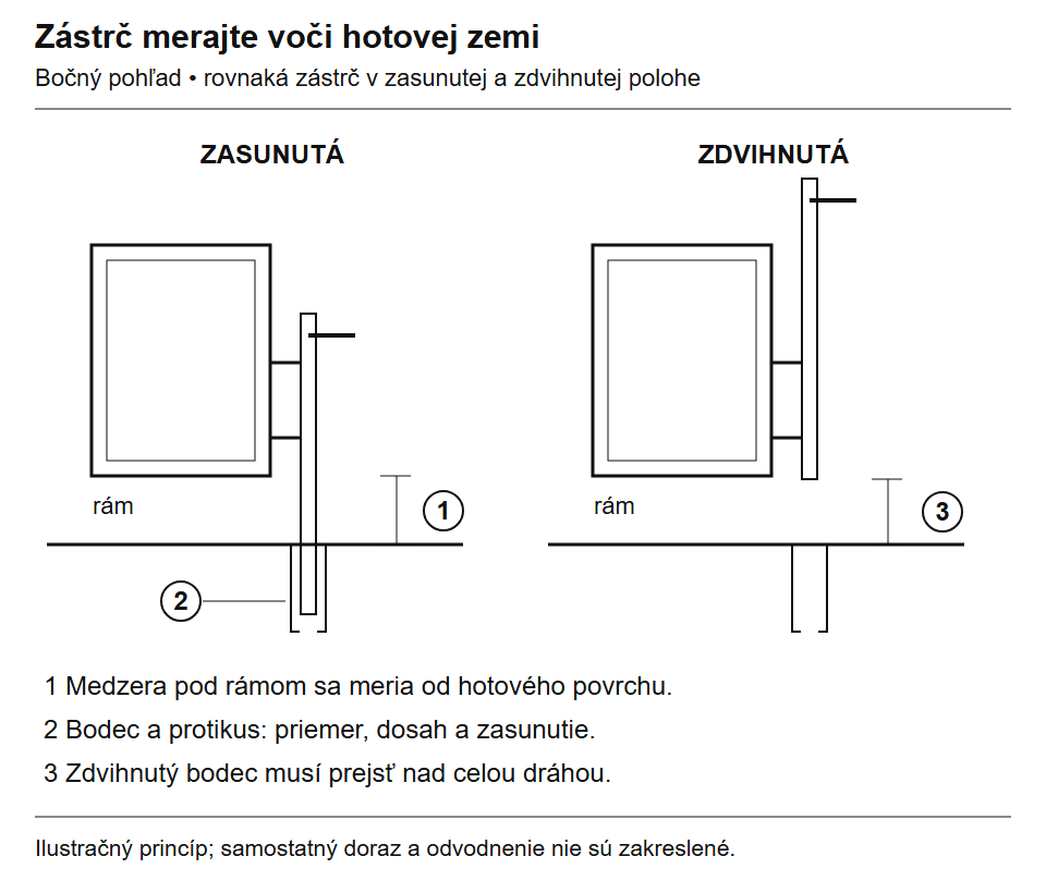
Measure both the engaged and raised positions. When raised, the bolt must not catch on a higher point in the driveway. Click to enlarge.
EGS socket or SABO stop?
EGS is a recessed socket for the bolt, with a water drain. It has no stop plate, so it does not determine the final gate-leaf position on its own. SABO combines a bottom stop with an opening for the gate bolt. Choose it based on the gap between the finished ground and the bottom edge of the gate leaf, the bolt dimensions, and the installation instructions.
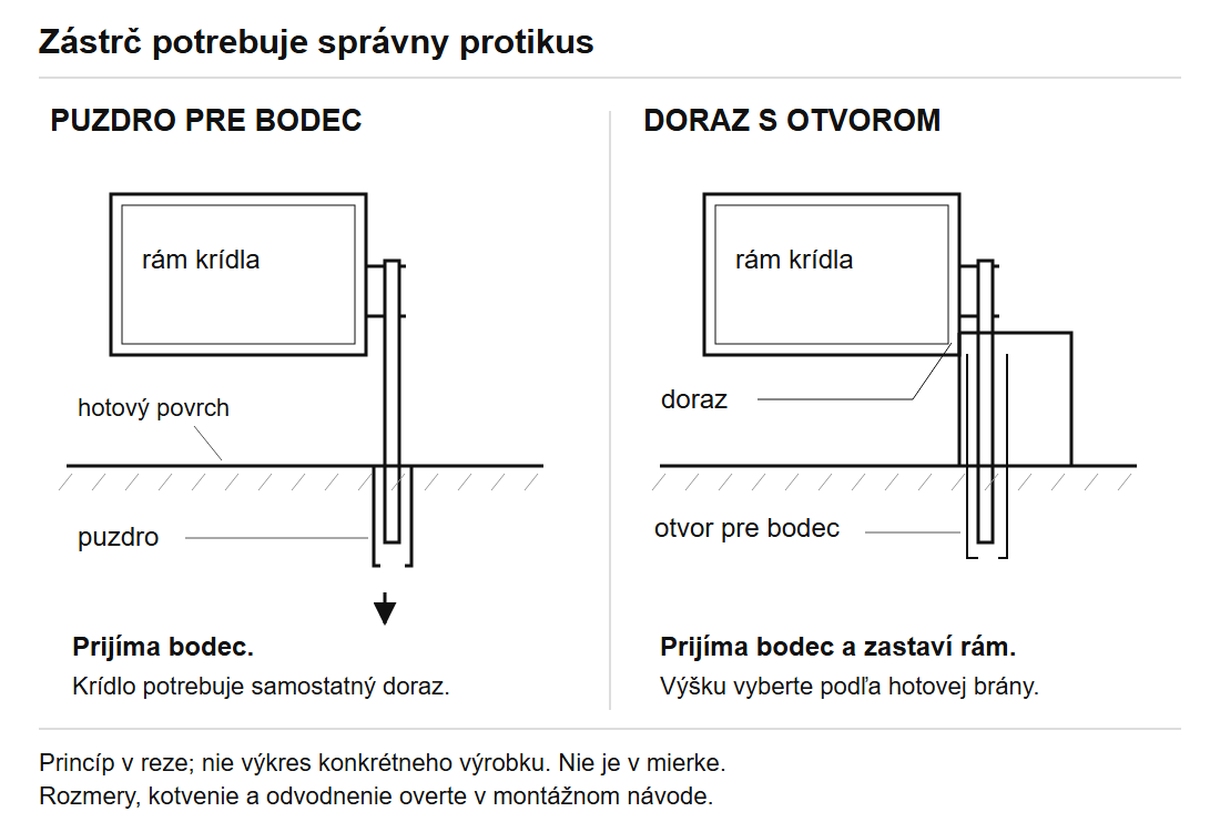
| Socket and stop from our range | |
|---|---|
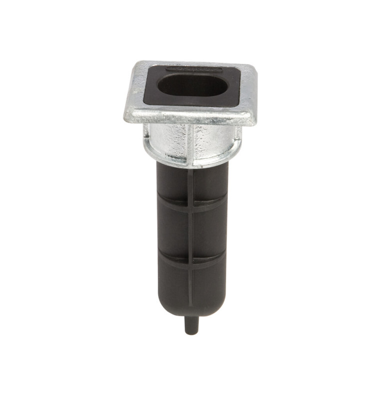 |
Locinox EGS – gate-bolt socket Recessed socket for the bolt, with a water drain. It has no stop plate; provide a separate solution for the final gate-leaf position. |
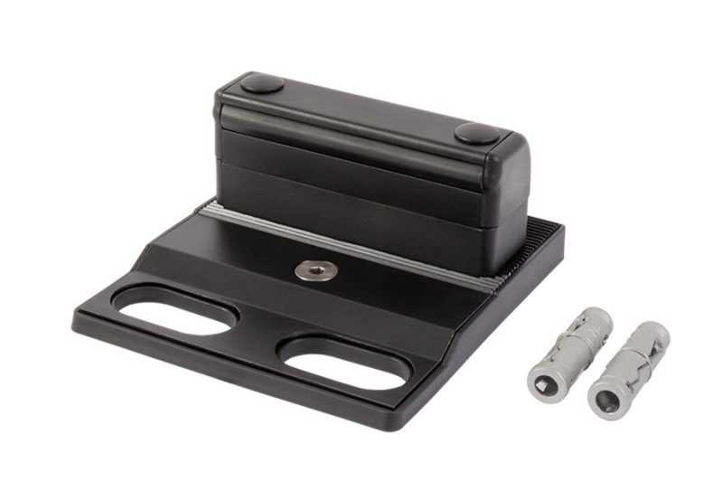 |
Locinox SABO – stop with opening Bottom stop with an opening for the gate bolt. Choose based on the gap above the finished paving and the bolt dimensions. |
Two examples of securing a manual gate
| Situation | Parts and checks before ordering |
|---|---|
| You already have a stop, but need an opening for the gate bolt | Gate bolt + recessed EGS socket. EGS is for bolts up to Ø 20 mm and has no stop plate. Measure the bolt's reach, the height of the finished paving, and the space available for installation with drainage. |
| You need both a stop and a surface-mounted keep | Compatible gate bolt + SABO. Check that the bolt is up to Ø 20 mm and that the gap between the surface and the bottom of the gate is 20–45 mm. For VSA, VSF and KEYDROP, the manufacturer specifies a 40–60 mm profile; this is not a universal combination for every gate bolt. |
With either solution, check that the bolt is clear of the entire travel path when raised, and that each opening leaf has suitable securing hardware. If you plan to add an operator later, adapt the manual locking system for automatic operation.
Lockable gate bolt or installation in the frame
A stop alone, or a standard non-lockable gate bolt, will not lock the gate. Choose a lock or a lockable gate bolt, such as KEYDROP. For concealed SUBY installation, first check the profile's internal space and wall thickness; prepare the mounting hole according to the product drawing.
| Locking and profile installation | |
|---|---|
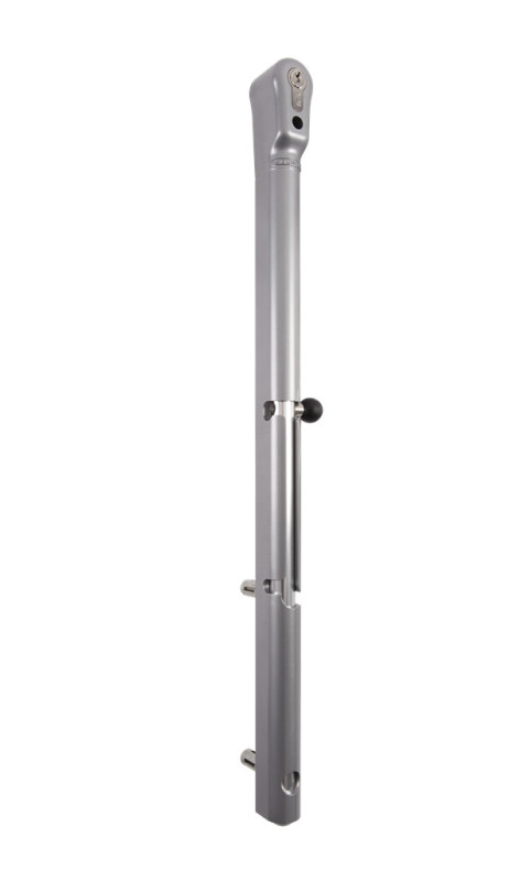 |
Locinox KEYDROP – lockable gate bolt Gate bolt lockable with a key. Check the available space on the profile, the required bolt travel, and the position of the keep. |
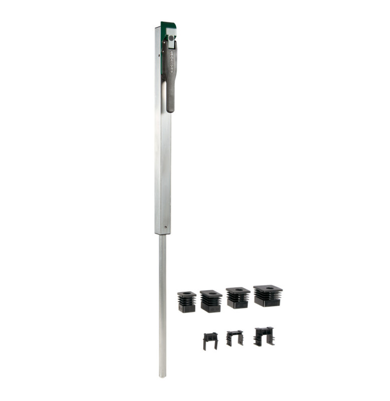 |
Locinox SUBY – profile-mounted gate bolt Gate bolt fitted into the gate-leaf profile. Before cutting the hole, check the profile, wall thickness, and installation drawing. |
Locinox VSF has a different configuration: when the gate is closed, its handle may be blocked by the other leaf. Do not confuse this locking method with installing SUBY inside the profile. Find more sizes and versions among our gate bolts for swing gates.
The electric lock must be compatible with the operator
Check the lock requirements before preparing the wiring. For M-Fab, the manufacturer recommends an electric lock for leaves wider than 2.5 m; this is not a general threshold for all motors. For other operators, follow the relevant product instructions.
NICE PLA10 is a vertical and PLA11 a horizontal electric lock; both use 12 V AC. Check the output and control method in the instructions for the control unit actually installed. The motor voltage does not determine the power supply for the lock.
An electrically operated bottom bolt is another option. It must fully unlock before the gate leaf moves and engage only when the leaf is in the correct position. Check the required power supply, control signal, keep, and emergency release method.
In the event of a power failure depending on its design, an electric locking system may remain locked or release. Check the specific model's operating characteristics and access to the key. Unlocking the gate bolt will not release a blocked motor; also see manual release and operator backup.
The overlap determines the order in which the leaves move
If one leaf has a cover strip that overlaps the other, it must be released first when opening and close last when shutting the gate. Test this movement manually first. Then set the correct sequence and delay in the specific control unit; do not guess the motor numbers based on the left and right sides.
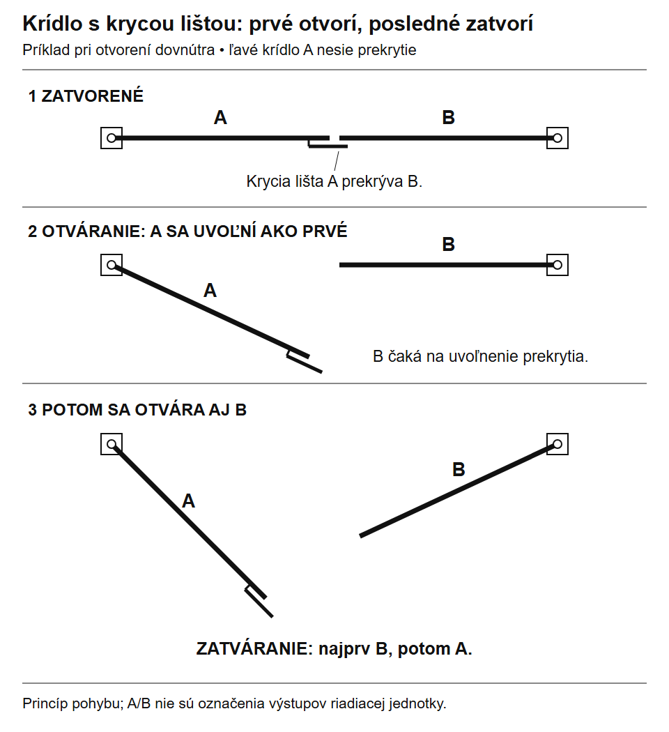
In this example, the left leaf A carries the strip; with the overlap reversed, the roles are reversed. Refer to the control unit instructions for motor numbers and delay settings. Click to enlarge.
For a manual setup, first close and secure the passive leaf, then close the active leaf. The stop and keep must align in this position. The lock or gate bolt must not be used to force a sagging or twisted frame back into alignment. For unequal-width leaves assess each motor and its travel path separately.
How will you operate the gate every day?
Check what is included in the operator kit before ordering. The receiver, remotes, photocells, or warning light may already be included. Choose accessories based on the exact control unit model and who will use the gate.
Position the button or keypad so that the user stands clear of the gate leaf and operator arm while entering a command. An electric key switch sends a command to the control unit; it does not replace the mechanical release key during a power failure.
| What | Why | Type and checks |
|---|---|---|
| Key switch | Operate the gate at the entrance without a remote control. | Switches: contact and wiring must match the control unit input. An electrical command is not a mechanical emergency release. |
| Keypad | Code-based access for household members or authorised visitors. | Check the wired, bus, or radio interface and any decoder in the control system. |
| Mobile phone control | Open the gate and manage access, depending on the module's capabilities. | GSM or Wi-Fi solution: signal, power supply, connection to the control unit, and any SIM/service. An open command may not confirm the gate's actual position. |
| Backup power | Operation during a power outage with a supported setup. | Backup for the specific control unit. Check the connector, charging, and accessories; it is not compatible with all 24 V motors. |
| Remote control | An additional user or control for multiple devices. | Check the receiver, encoding, and frequency. The same frequency alone does not confirm compatibility. |
Choose safety devices according to the location
Photocells monitor their beam path. They do not replace an assessment of areas around the hinges, between the leaves, and by the fence. Choose the interface for photocells and safety edges, and how they are monitored, according to the control unit and the gate’s risk areas. Choose the beacon’s power supply according to the controller output.
Frequently asked questions about choosing parts
Do I need a stop even on a gate with an operator?
Follow the instructions for the specific motor: it may use an external or built-in mechanical stop for that direction. Teaching the travel limits does not mean you can omit the specified stop. Check both the open and closed positions.
Is a spring-loaded bolt automatic?
A spring does not, by itself, mean electric unlocking. With a standard manual bolt, the operator must release the gate leaf before starting the operator. For automatic locking, choose a device that works with the controller.
Will a wheel help if the gate leaf is sagging?
First find the cause: hinges, frame, anchoring, or post. Support wheel It can support a gate designed for it; it is not a general-purpose repair for the gate’s mechanism.
What to check before ordering
- Profile dimensions and a solid mounting point for the part.
- The finished clearance beneath the gate leaf, the bolt diameter and travel, and the keeper.
- Opening direction, overlap, and access to the handle or key.
- For an electrical component, the exact control-unit model, power supply, interface, and behavior during a power outage.
- Kit contents, anchoring, cables, and parts ordered separately.
Send us a photo of where the gate leaves meet, the stop location, and the profile dimensions and ground clearance. For an automatic gate, include the operator nameplate and control-unit model. We’ll help you choose compatible parts.
| Continue based on what you need to resolve |
|---|
| Measuring and choosing an approach · All situations and examples |