The gate needs clear space throughout its entire opening arc, not just a wide enough opening between the posts. Before choosing the gate leaves, check the terrain, where the parked car will be, and the space needed for the opener. You’ll find the basic measurements in the introductory guide.
| Swing gate: choose a topic | |
|---|---|
| Measuring and procedure | |
| Space and slope | Frame, hinges and infill |
| Opener and brackets | Stops and accessories |
Measure from the finished surface: allow for the future paving, post cladding and the position of the selected hinge axis.
How much space a gate leaf really takes up
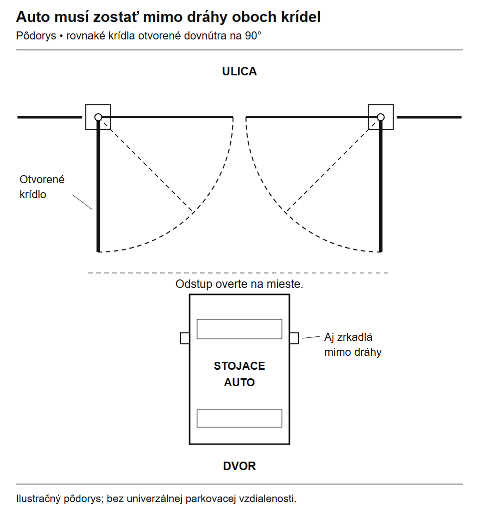
Both leaves are the same length in every position. Extra space is needed for the hardware, the opener body and safe operation. Click to enlarge.
The gate leaf does not slide sideways. It pivots around the hinge axis, and its far corner traces an arc. With one long leaf, this arc is large, and the entire leaf is supported on one side of the entrance. With two leaves, the opening is split between them, so each needs a shorter clear path. However, a double-leaf gate requires two openers for automation, two supporting posts and usually wiring to the opener on the opposite side. See the front-view drawing and the basic measurements.
Measure from the hinge axis, not from the edge of the post. The axis position changes depending on the hinge selected and how it is installed. A leaf hung from the inside edge of the post may provide a wider clear opening, but it needs a different clearance by the post and may change the position of the opener bracket. If you move the hinge, the arc drawing and the motor mounting dimension will no longer be valid.
At the finished entrance, carry out a simple check:
- Mark the future pivot axis of both leaves. Allow for the finished post cladding and the thickness of the surface finish.
- Measure the distance from each axis to the farthest plan-view corner of its respective leaf. Allow for the hardware and any overhangs; the movement radius is not half the opening between the posts.
- Mark the arc on the ground using string, a straightedge or a tape measure. Check the full intended opening angle. Check for walls, fences, steps, planters, downpipes and the place where the car will be parked.
- Check the space needed for the opener and its arm or body. Having clearance for the leaf does not necessarily mean there is room for the automation system. Articulated-arm, linear and underground operators all have different space requirements.
Check the car in two positions: in front of the closed gate and behind the open gate. There may be enough room for the gate’s arc itself, but the open leaves could extend into the space where you need to maneuver the car after turning off the road. If the garage is close to the gate, also check the clearance for the parked car’s open doors.
Will there be enough room for the car once the gate is open?
The opening between the posts and the usable passage may not be the same width. At the intended opening angle, check the projecting leaf, hinges and opener. Mark the car’s outline on the ground, including the mirrors, and test the approach from a turn as well. Assess a longer van or trailer based on its actual path.
Example: a short driveway: the car stops in front of the garage after entering. Mark its outline and the arcs of the gate leaves on the ground. Check whether the gate can close behind the car and later open without hitting the bumper. If not, compare moving the gate, changing the leaf configuration, or using a folding or sliding system.
Common mistake: There is 90° of clearance in the plan view, so an opener is ordered automatically. Then there may be nowhere to anchor the bracket, or the motor may hit the leaf when it opens. First determine the hinge axis and the required opening angle, then check the installation drawing for the exact opener.
Measure the driveway slope in both directions
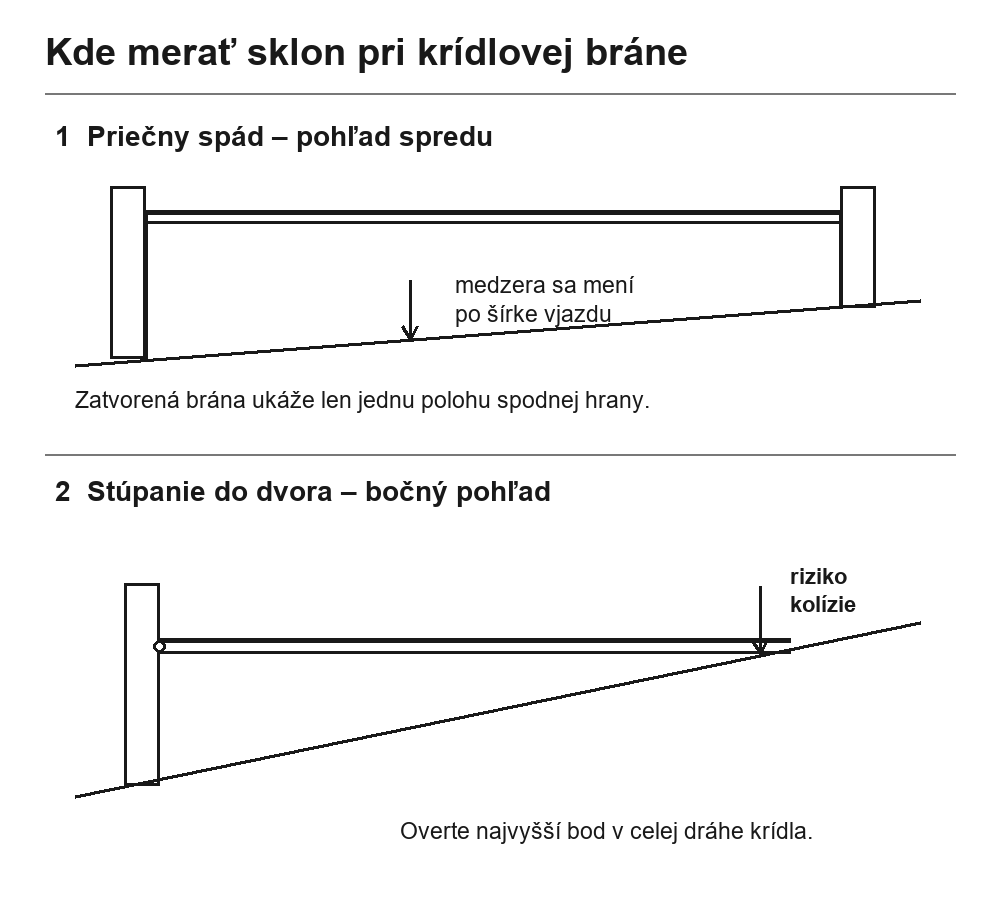
With a slope, the critical factor is the smallest clearance along the entire path, not just the gate’s closed position. Click to enlarge.
A “sloping driveway” can mean two different things. Cross-slope runs from one post to the other. Uphill gradient runs from the road into the yard. They often occur together, and their effect changes as the gate opens.
Cross-slope
With a cross-slope, you can design the bottom edge of the frame to follow the surface where the closed gate sits. However, this only proves that the closed gate will not scrape the ground. As the leaf swings, its bottom edge passes over different points in the yard. With a double-leaf gate, the two leaves also start at different heights and must meet correctly at the central stop. What matters, then, is the minimum clearance throughout the entire path, not just the gap beneath the closed leaf.
Uphill gradient into the yard
On an uphill gradient from the road, a gate leaf on standard vertical hinges moves at essentially the same height while the ground beneath it rises. Even a slight uphill gradient can stop the gate from opening after a few dozen degrees. A more powerful motor will not solve this problem; it will only push the leaf against the obstacle.
For the measurements, all you need is a laser or hose level, a tape measure and a sketch:
- On the drawing, mark the finished surface level along the axis of the closed gate. If the paving has not been laid yet, mark its final level. In that case, measuring the current soil level is only preliminary.
- Mark the swept area of each leaf. Measure the ground level by the post, about one-third of the way along the leaf and at its far edge, at several points up to the planned open position. Take more measurements around drains, raised paving slabs or changes in slope.
- Compare the highest point found with the bottom edge of the leaf in that position. If the frame is sloped, checking just one corner is not enough: the entire bottom edge matters, as it projects onto a different part of the ground as it swings.
- Allow a sensible operating clearance for the finished surface, water drainage, dirt and winter conditions. There is no single universal figure for the clearance; it depends on the terrain, infill and stop.
If you cannot determine from the drawing whether the sloped frame will hit the ground as it opens, it is cheaper to prepare a simple plan and elevation section or a movement model than to shorten the finished leaf after welding. If there is a significant cross-slope and uphill gradient, it is worth having the whole area surveyed.
Measurement example: paving rises into the yard
You measure 80 mm beneath the closed leaf. At the point where its bottom edge will pass, the finished paving is 100 mm higher. With a horizontal frame on vertical hinge axes, this already creates a collision—the clearance is 20 mm short, even before allowing for operating clearance.
- Compare several points this way across the entire swept area. Use the planned finished paving level instead of the current ground level.
- First assess the gate position and any changes to the terrain. Then compare opening outward onto your own property, a different leaf configuration or another type of gate.
- Recheck the final design against the frame, stops and operator geometry. A more powerful motor or a standard support wheel will not give the leaf a clear path.
Related components and guides: outward opening, folding systems, wheel requirements.
When inward opening is not feasible
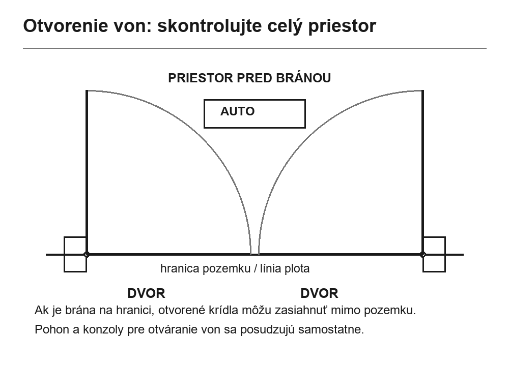
For outward opening, measure the space in front of the gate and the property boundary. Click to enlarge.
One possible solution is to change the gate position or the leaf configuration. Consider a larger gap beneath the frame only after checking the appearance, safety, and bottom stop. If the gap would be excessive, don’t deal with the terrain simply by raising the entire gate.
Outward opening may help where the driveway rises steeply just beyond the gate. However, it requires space in front of the gate. Before planning, check the property boundary, space for pedestrians and vehicles, and the conditions for connecting to the road. The open leaf must not create an obstruction beyond the area you are entitled to use. For a gate set farther back on the property, also check that there is room in front of it for a car to stop safely.
With automation, outward opening changes the bracket positions, the direction of force from the operator, and possible collisions with the gate leaf. With Wingo and Toona linear actuators, the usual solution involves an extended NICE PLA6 rear bracket. Check whether it is needed and where it should be positioned against the installation diagram for the selected model; the same solution does not automatically apply to articulated-arm or underground operators. See the check of the installation dimensions.
When a standard gate leaf gets in the way as it opens
Rising gate leaf
Rising gate leaf rotates and rises at the same time as it opens. It can clear rising terrain, but it changes the position of the entire leaf: the top edge may come closer to the wall or fence, the centre of gravity and the force needed to move it change, and the operator works differently than on a standard vertical axis. This solution requires the hinges, end positions, stops, and suitability of the specific operator to be confirmed as part of the design. It is not enough to buy an adjustable hinge and move its lower pin away from the upper one “according to a formula.”
Folding gate
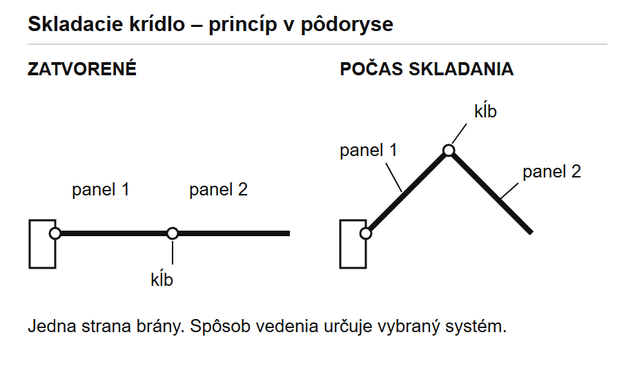
As the gate opens, the outer panel folds toward the panel by the post. Use the drawing for the selected mechanism during installation. Click to enlarge.
Folding gate can be useful when there is not enough depth for two standard leaves or enough space beside the fence for a sliding gate. The panels fold as they move, so they need a smaller continuous area in front of or behind the entrance. However, this adds hinges, a mechanism to coordinate the panels, and pinch points. Even with a folding design, check the slope, wind exposure, clear passage, and access for servicing. A standard operator for a single leaf is not automatically an approved setup for a folding mechanism.
For a folding system, compare: the dimensions and weight of both panels, the position of the folding joint, the required angle, and the space by the post. There are different systems for opening to approximately 90° and for folding farther back toward the fence. Check whether the specific kit requires a floor guide and which operator its manufacturer permits. The characteristics of one kit do not apply to all folding gates.
To compare this option for your entrance, see mechanisms for folding swing gates. For a double-leaf gate, you need a solution for both sides, and the operator must be selected for the actual construction.
If there is enough clear length along the fence, also compare cantilever sliding gates and their components. On a steep slope where there is no room for a swing arc, a sliding gate may be a better choice, but it needs its own side track, supporting structure, and foundation preparation. Choose the gate type based on the site, not on which operator has the biggest number on its spec sheet.
Example: 4 m clear opening and 1.5 m high frame
Using an example with a 4,000 mm opening and a 1,500 mm-high frame we’ll show how to check the available space. Take the leaf lengths from your drawing with the selected hinges; the illustrative opening alone does not determine the frame dimensions.
Example scenario: the leaves are to open inward by 90°, there is a low wall two metres away, and the paving rises from the road.
- Mark the arc of the entire leaf from the actual hinge axis. A space of about two metres does not by itself confirm that the frame, fittings, and operator will fit.
- Measure the finished paving height throughout the entire swept area. Check the bottom edge of the frame, not just its far corner.
- If there is a collision, compare moving the gate, using a different leaf configuration, or opening outward. Only then assess a rising or folding system.
Next, consider a single four-metre leaf. It would eliminate the meeting point in the middle and the second operator, but it would need a considerably larger clear area and put a much greater load on a single supporting post. For this type of entrance, it is therefore not automatically the simpler or cheaper option. The actual suitability depends on the design of the frame, post, hinges, and specific operator.
Two gate leaves of different widths and a pedestrian entrance
If you often walk through, also consider a separate pedestrian gate. You won’t need to move a large gate leaf every time you pass through. Check its clear opening, opening direction, and space beside the car on your drawing.
A narrower leaf can provide a more convenient everyday passage, while a wider one clears the entrance for a car. Measure the usable width at the actual opening angle and the space needed for the wider leaf to swing. Assess its hinge, post, and operator separately; the overall opening width is not enough.
If the leaves overlap, decide which one opens first and closes last. With automation, also check whether one leaf can open independently and how it is protected by the control system. Partial opening alone does not guarantee safe passage for pedestrians.
If a small pedestrian gate is built into a large leaf, the operator must be interlocked so it cannot run while the pedestrian gate is open. Select the safety devices and wiring for the specific system before manufacturing.
What must be clear before manufacturing
| What you have established on site | Why it matters |
|---|---|
| Finished distance between the posts and the planned axis of each hinge | These determine the frame and the actual opening arc. |
| Opening direction and required angle | These determine the clearance, stops, and operator mounting geometry. |
| Surface heights throughout the path of both leaves | They reveal collisions that are not visible when the gate is closed. |
| Positions of parked cars, pedestrians, and fixed obstacles | The gate must work in everyday use, not just in a test with no car present. |
| Infill type and approximate weight of each leaf | These affect the posts, hinges, wind load, and operator selection. |
| Space for the bracket, body, or arm of the selected operator | Without this, the specific automation setup cannot be confirmed. |
Once you have measured the site, check together the gate leaf construction and the space for the operator. Only then finalize the manufacturing drawing and construction preparations. For an unusual entrance send a sketch and photos showing the hinge positions, dimensions, and terrain heights.
| Continue based on what you need to work out |
|---|
| Frame, hinges, and infill · All scenarios and examples |