The frame, hinges and posts form a single unit. For a new gate, include the infill and chosen operator in the design from the outset: its brackets need a secure mounting point and the correct distance from the hinge axis. The following recommendations will help you take measurements and choose components; the dimensions of load-bearing parts must be determined for the specific gate leaf and mounting surface.
| Swing gate: choose a topic | |
|---|---|
| Measuring and procedure | |
| Space and slope | Frame, hinges and infill |
| Operator and brackets | Stops and accessories |
Before cutting: determine the frame length based on the finished clear opening and the selected hinges. Mark the crossbar, infill fixings and the operator’s front bracket at its actual height.
Frame, crossbar and posts
The gate leaf transfers its own weight through the hinges to the post and foundation. Wind and the operator add further forces. When designing the gate, simply choosing a box section is not enough: the leaf length and height, frame stiffness, infill, hinge positions and bracket fixings all matter.
Box sections and frame crossbar
For a small gate leaf of around 2 m or less with lightweight, open infill, you could also consider a 40 × 20 × 2 mm box section. However, a 2 m length does not confirm this profile’s load capacity or provide a specification for the entire frame. When choosing from our structural profiles compare the cross-section, wall thickness and profile orientation in the frame. Give the frame manufacturer the leaf dimensions and weight, the infill fixing method, and the operator bracket location.
| Profiles in our range | |
|---|---|
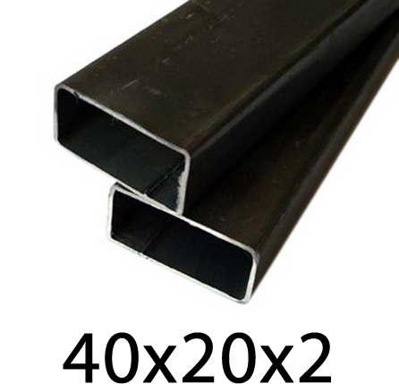 |
For lightweight, smaller structures; before using it for the perimeter frame, check the stiffness and load of the entire gate leaf. |
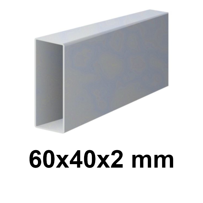 |
Galvanised profile, 60 × 40 × 2 mm Rectangular cross-section with 2 mm walls. Mark on the drawing which way the wider side will face. |
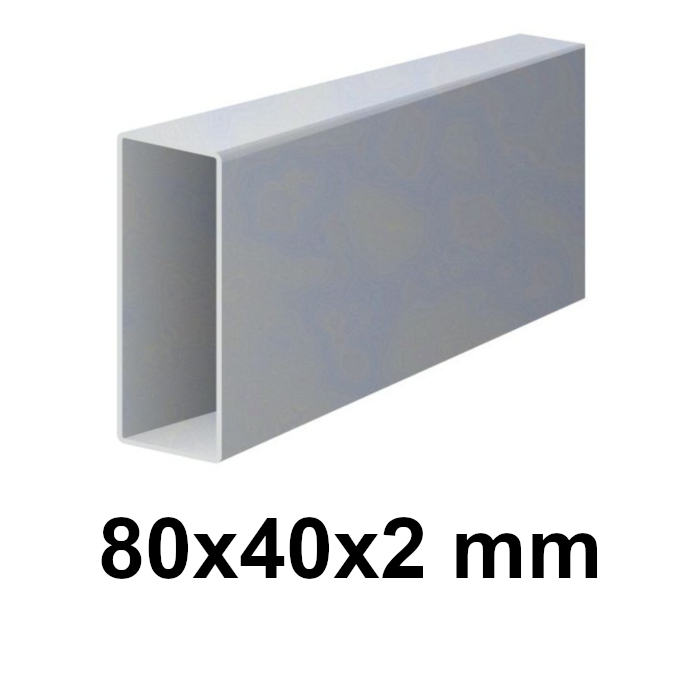 |
Galvanised profile, 80 × 40 × 2 mm A taller profile with the same wall thickness. Compare stiffness, frame weight and space for the fittings. |
In the 4 × 1.5 m example, each leaf has one horizontal crossbar in the lower third. Before fitting it, check the spacing of the infill supports and the height of the operator’s front bracket. If the crossbar is also to support the operator, it must transfer its forces to the frame; do not determine its position based on appearance alone.
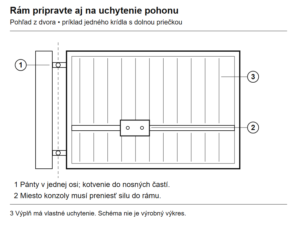
The bracket position is determined by the operator’s installation drawing. The lower crossbar in this example is not a universal mounting height. Click to enlarge.
Example: manual gate now, operator later
4 m clear opening, 1.5 m-high frame and lightweight, open infill. You want to open the gate manually at first, then add operators once the yard is finished.
- Measure the finished opening and choose the hinges. Only then determine the width of both frames based on their hinge positions; a gate leaf of approximately 2 m does not mean a 2 m cutting length.
- Compare the installation dimensions of the operator you are considering now. Prepare load-bearing mounting points for the brackets on both the post and the gate leaf, and a cable conduit beneath the driveway.
- For manual operation, choose stops, a way to secure the open leaves, and a drop bolt with a keeper. Before operating the motor later, the manual locking mechanism must be released or replaced with a suitable solution.
Related parts and instructions: profiles, hinges, drop bolt and keeper, conduit preparation.
Post and foundation
Post for a Wingo or Toona linear operator: For a steel structure, we recommend allowing space for a 120 × 120 mm post, or 100 × 100 mm if the specific geometry permits. The position of the hinge axis and bracket pin is determined by the operator installation drawing and graph. With a different cross-section or position, a modified or extended PLA6 bracket, if the selected model allows it.
This is a recommendation for bracket mounting space, not a structural minimum. Determine the wall thickness, anchoring and foundation based on the gate leaf, infill, wind and mounting surface. For HOPP with articulated arm check the available space against its own drawing.
Fix the hinges and brackets to the load-bearing part of the post, not just to its cladding. For anchors, check the substrate type, anchoring depth and specified distances from edges. For an existing masonry post, find out what lies beneath the cladding. Foundation design requires information about the soil, water and local frost conditions, so one universal excavation size is not enough.
It is practical to have the conduit runs prepared before pouring the concrete. An underground operator requires construction work for the specific foundation box, including water drainage. Concrete curing time and anchor loading must be based on the design and materials used.
Surface finish and infill installation
Before applying a surface finish, it is worth assembling the frame with the fittings as a trial and checking its geometry. Surface protection, coating repairs at welds, and drainage or vent holes depend on the system selected. For hot-dip galvanising of closed profiles, agree on the required holes with the galvanising plant before fabrication. The infill supplier will specify its recommended fixing method.
How to choose hinges and fixings
When replacing an existing hinge: Before removing it, photograph the entire fixing and a close-up. Note the pin or thread diameter, hole spacing and distance from the post to the axis. The same thread with a different offset can change both the gap at the post and the operator geometry.
Choose the complete hinge assembly: hinge, pin or mating part, and fixings to both the post and frame. An M16 or M20 thread alone does not determine the load capacity of the entire assembly.
| What to compare | What to check before ordering |
|---|---|
| Gate leaf | Length from the hinge axis, total weight including the infill, and spacing between the upper and lower hinges. The load capacity must apply to this combination. |
| Fixing | Plate dimensions and holes for bolting; suitable load-bearing material for welding. The hinge must not be anchored only to the cladding. |
| Position and adjustment | Gap at the post, adjustment range and space for the nuts. After the surface finish is applied, there must still be room for adjustment and locking. |
| Mating part | The exact pin dimensions or a matching part recommended for the selected hinge. When replacing it, send a photo of the complete pair. |
An adjustable hinge helps fine-tune the gate leaf position, but once adjusted it must be properly secured, with the thread engaged to the specified depth. Do not add together the load capacities of two catalogue items; check whether the manufacturer specifies a rating per item or for the assembly, and at what spacing.
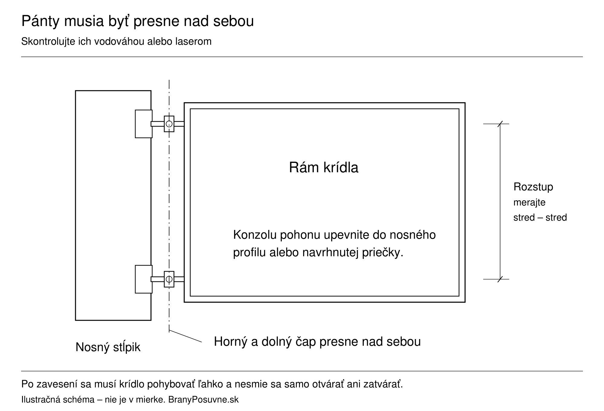
The upper and lower pins must be exactly in line. Measure the spacing between the pin centres; a spirit level or laser makes it easy to check that they share an axis. Click to enlarge.
| Type | When to consider it | What to check |
|---|---|---|
| Adjustable plate-mounted | Screw-fixed to a suitable substrate. | The plate, holes, anchors, adjustment range and drive clearance. |
| Adjustable weld-on | Steel frame and load-bearing steel post. | The weld, alignment, locknut and corrosion protection after welding. |
| Axial C hinge | A structure with the corresponding pin in the profile. | The correct pin, profile, installation and load-bearing conditions. |
| Special / offset | Special geometry or gate-leaf lift. | The entire travel path and explicit confirmation that it is compatible with the drive. |
| Related products | |
|---|---|
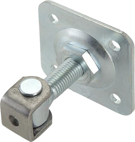 |
Measure the space for the plate and the hole spacing. Choose the thread size and anchors to suit the actual load-bearing substrate. |
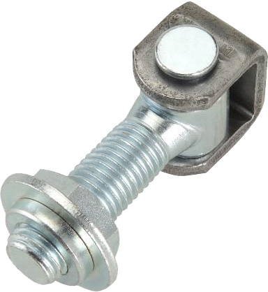 |
For a suitable steel structure. After adjustment, secure the thread and restore the surface protection. |
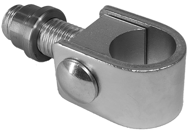 |
Choose together with the CAIS HP40 pin for welding into the profile. For the complete hinge system, also check the upper and lower supports and the adjustment method. |
At the same weight, a wider gate leaf puts different loads on the hinges than a narrow one. If the product specifications do not cover your gate-leaf length and hinge spacing, have its suitability confirmed before ordering.
See the full range in the hinges and fittings for swing gates. The final opening angle is affected by both the hinge and the geometry of the installed gate drive.
When to consider a support wheel
Choose a wheel only after checking its travel path. Check the route where it contacts the ground, including joints, drainage channels and changes in slope. If it loses contact or catches on part of the arc, the load on the hinges and the resistance to movement will change.
A support wheel may form part of the planned gate-leaf support. It needs a firm, traversable surface along the entire arc; gravel, a kerb or sunken paving can restrict its movement.
Measure height differences along the path and compare them with the wheel's design. The spring travel is limited, and the wheel's load capacity is not the permissible weight of the entire gate. For an automated gate, confirm that support is permitted for the specific setup. If the gate leaf is already sagging, first fix the cause in the frame, hinges or post.
Infill: appearance, weight and wind
Infill is an integral part of designing the frame and choosing the drive. The total weight of the gate leaf includes the frame, bracing, infill, fasteners and fittings.
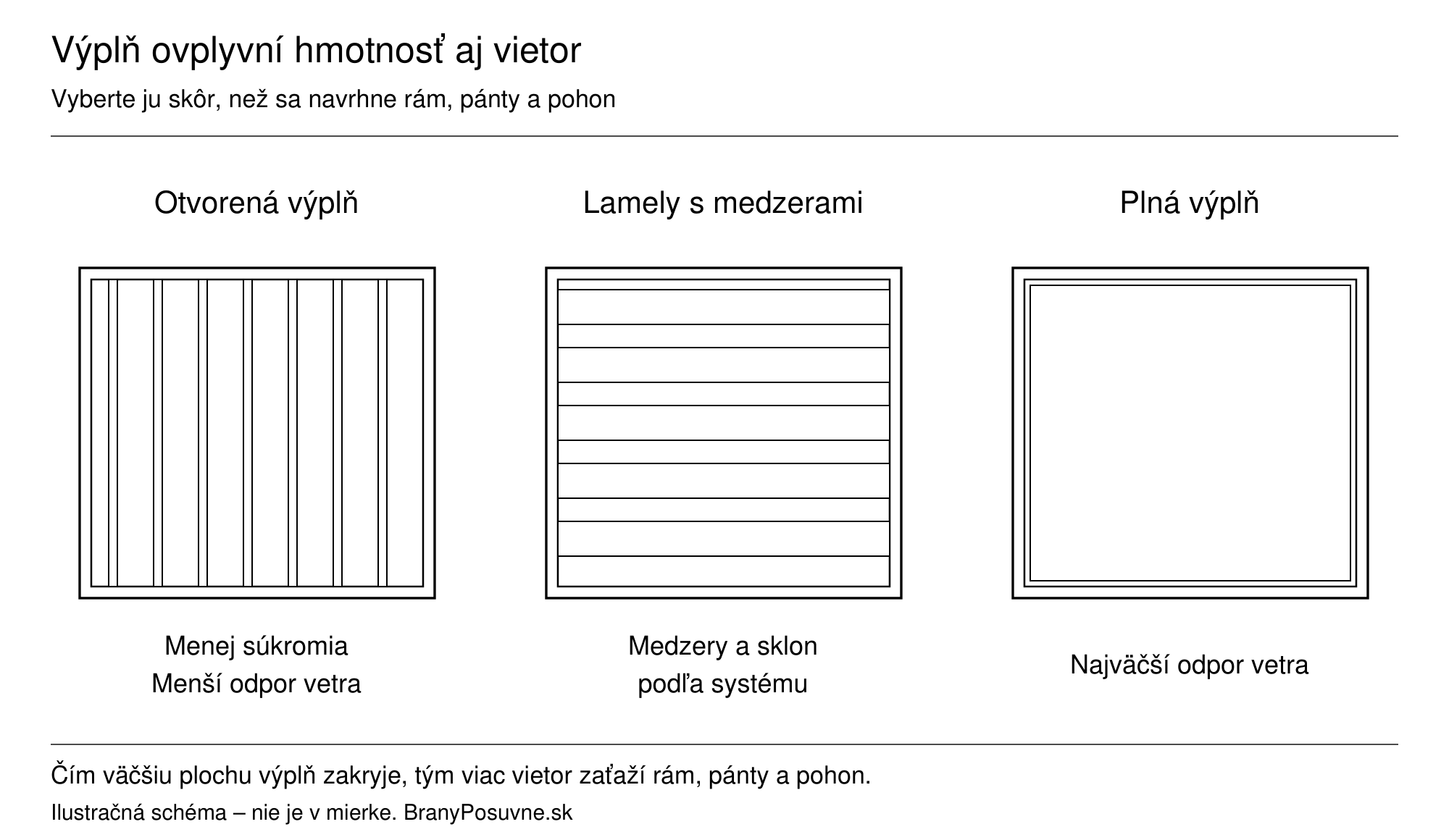
The more surface area the infill covers, the more wind loads the frame, hinges and drive. That is why infill is one of the first factors to consider when sizing the other components. Click to enlarge.
| Infill | What to consider when choosing |
|---|---|
| Aluminium slats | The weight of the specific profile, support spacing, fastening, thermal expansion and isolation of dissimilar metals. |
| Galvanised board profiles | The total weight and how to restore protection where the material is cut or welded. |
| Z-profile slats | The correct combination of slat and support system. The angle and overlap affect visibility and airflow. |
| Wood, WPC and other infill materials | Weight, expansion or moisture-related movement, specified support and expansion gaps. |
| Related products | |
|---|---|
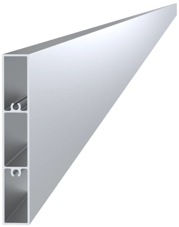 |
Check the infill instructions for support spacing, fastening and expansion gaps. Calculate the infill weight from the number and length of the slats. |
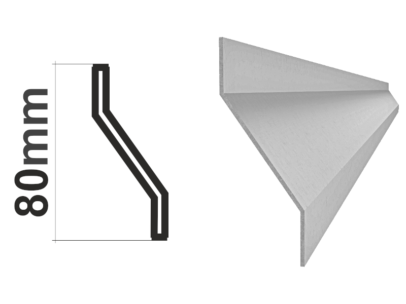 |
Part of a system with an S-size support profile and S1 footprint; all components can be selected as a compatible set. |
Solid infill in a windy location
Wind loads the entire gate-leaf area. If you add solid infill to a frame that was originally open, recheck the frame, hinges and posts, drive suitability and locking. For comparison, send the dimensions of each gate leaf, the type of infill and a photo of the surrounding area. A more powerful motor or a lock alone will not fix an inadequate structure.
Example: you want solid slats for an open frame
The gate opens easily now, but you want to reduce visibility from the street. The new infill will change both the weight and the area exposed to wind.
- Find out the weight of the infill, including rails and fasteners. Use the slat lengths and quantity to calculate the added weight for each gate leaf separately.
- Show the frame supplier how the infill is fastened, the cross-section and wall thickness of the frame, and the hinges and posts. Also check the required support and expansion allowance for the slats.
- For an existing drive, provide its type and a photo of the open entrance. Reassess the choice for wind loads; a motor that was suitable before may not be suitable for the new infill.
Related parts and procedures: infill comparison, drive limits, electrical locking.
Stops, drop bolts and locking
Plan the stop positions and locking method together with the frame. Allow a solid mounting point and room to operate the drop bolt or lock.
- Choose the closed-position stop to suit the bottom edge of the frame and the finished paving.
- An open-position stop and a gate-leaf catcher serve different functions.
- Choose a manual drop bolt together with its keeper; compare their dimensions.
Plan the locking system before completing the frame
For an automated gate, check in advance whether the drive requires an electric lock and how it must be wired. For overlapping gate leaves, determine the closing sequence. The manual drop bolt must not block the drive when it starts.
Test the gate manually before installing the drive
- On a flat surface, check the frame dimensions, diagonals and flatness before completing the welds.
- When positioning the gate, keep the hinge pins on the same axis. Test with the planned infill, not just with a light, bare frame.
- Check the full arc of both gate leaves. Check the clearance from the paving, post and fence, as well as the stop positions.
- The gate leaf should move easily without catching or moving by itself. Then recheck the prepared bracket dimensions and install the drive selected in advance.
If the gate leaf needs to be lifted when opening it manually, a more powerful motor will not fix a mechanical fault. Fix the cause before automating the gate.
Send us the gate leaf dimensions, infill type, and a photo of the post, if you’re unsure about the hinge, stop, or clearance for the bracket.
| Continue based on what you need to resolve |
|---|
| Drive, brackets, and preparation · All situations and examples |