Space
- clear opening width (ŠP),
- the side and direction in which the gate slides,
- clearance for the entire leaf, including the counterbalance,
- ground levels along the entire travel path.
Technical guide · DIY construction · cantilever gate
A practical guide for gates with a clear opening width of 7.0 to 10.0 m: two concrete foundations, cabling, carriages, guide system, operator, wiring, and technical drawings.
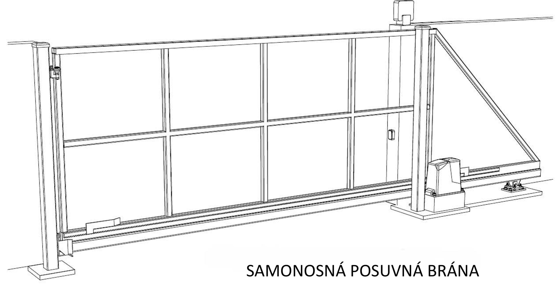
For a wider opening, the leaf length and weight, counterbalance, load-bearing C-profile, number of carriage rollers, infill, guide system, foundations, and operator must all be coordinated. The guide below starts with the construction work and continues in the order in which the individual components are actually prepared.
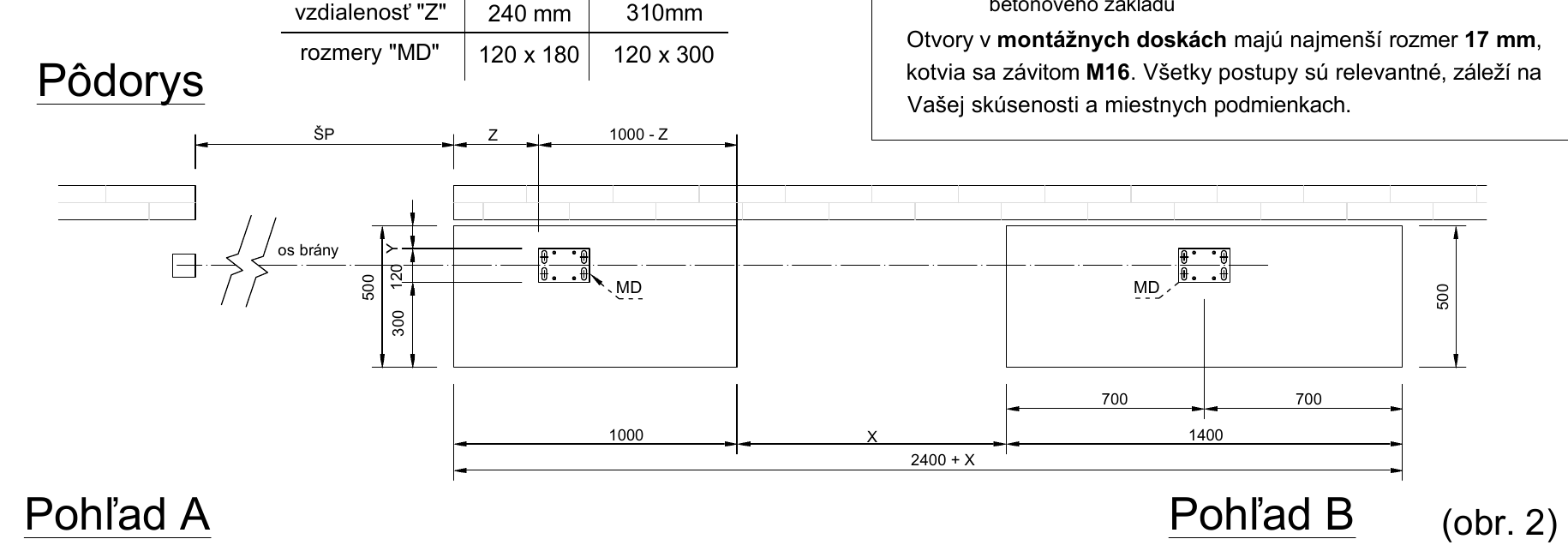
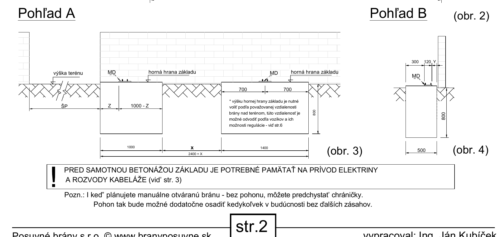
The source drawing for gates over 6.5 m uses two separate foundations. The foundation nearer the opening is 1 000 mm long, the second is 1 400 mm long, with a gap X between them. The total length of the assembly is therefore 2 400 + X.
| Clear opening width | Carriage with 8 rollers | Carriage with 10 rollers |
|---|---|---|
| 7 000 mm | 950 mm | 850 mm |
| 7 500 mm | 1 150 mm | 1 050 mm |
| 8 000 mm | 1 350 mm | 1 250 mm |
| 8 500 mm | 1 550 mm | 1 450 mm |
| 9 000 mm | 1 750 mm | 1 650 mm |
| 9 500 mm | 2 050 mm | 1 950 mm |
| 10 000 mm | 2 250 mm | 2 150 mm |
Bold values correspond to the recommended 10-roller option in the source drawing. Always read dimension X for the carriage actually used.
| Carriage type | Dimension Z | Mounting plate MD |
|---|---|---|
| 8 rollers | 240 mm | 120 × 180 mm |
| 10 rollers | 310 mm | 120 × 300 mm |
The mounting plate holes must be at least Ø 17 mm for M16 threads. Set the top of the foundation according to the required gate clearance above ground and the carriages’ height adjustment range.
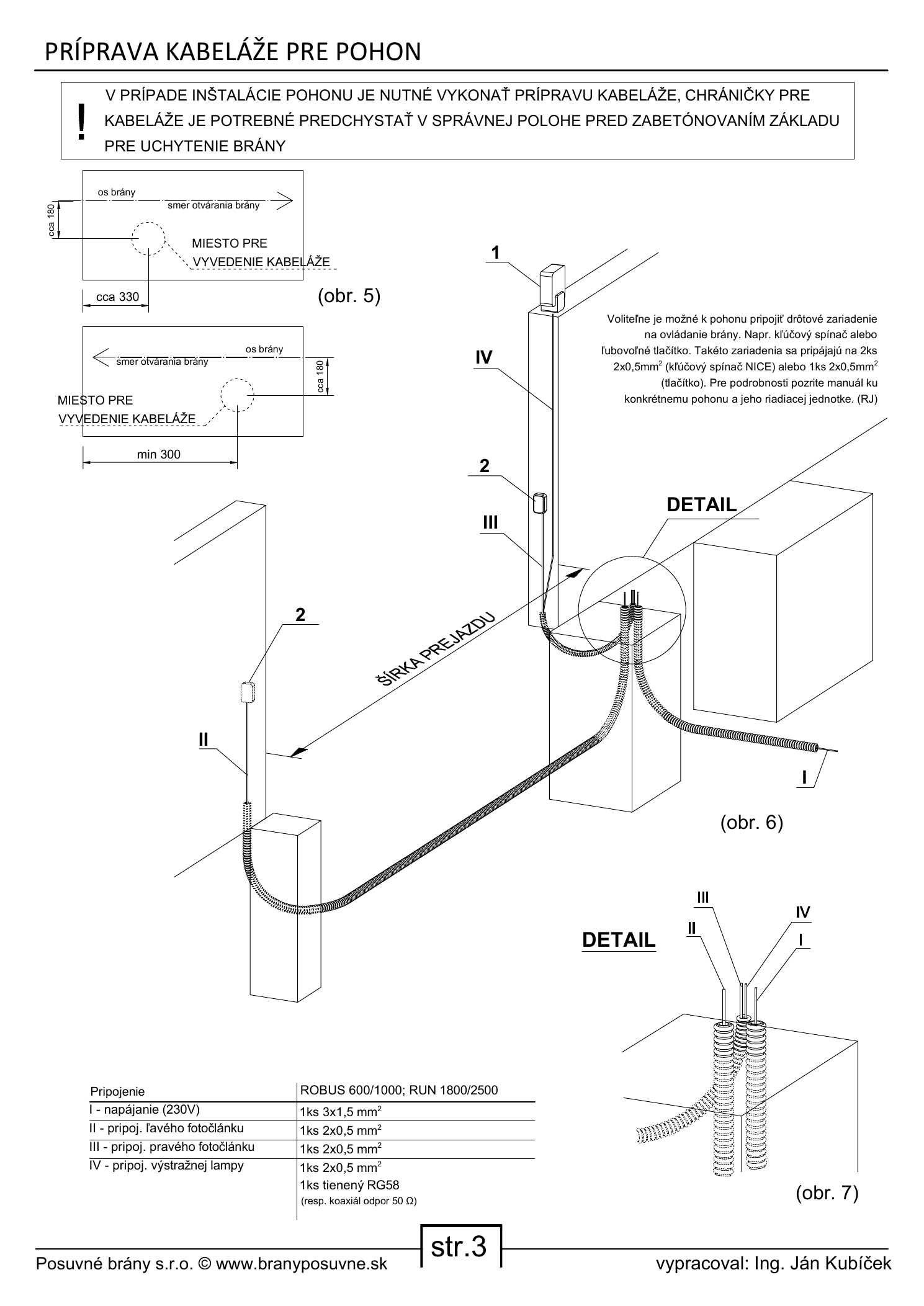
Install the conduits and cable outlets before pouring the concrete. The diagram below retains the complete original wiring description, including the power supply, photocells, warning light, antenna cable, and dimension notes.
| Label | Connection | Cable |
|---|---|---|
| I | 230 V operator power supply | 1 × 3 × 1.5 mm² |
| II | Left photocell | 1 × 2 × 0.5 mm² |
| III | Right photocell | 1 × 2 × 0.5 mm² |
| IV | Warning light and antenna | 1 × 2 × 0.5 mm² + shielded RG58 / 50 Ω coaxial cable |
The gate leaf must be guided from above or from the side, and the carriages must match the selected C-profile. Height H, measured from the top edge of the foundation to the bottom edge of the C-profile, is determined by the carriages used and their adjustment range.
| C-profile | 3 rollers | 5 rollers | 8 rollers | 10 rollers |
|---|---|---|---|---|
| 70 × 70 × 4 mm | 78–98 mm | 95–115 mm | 90–110 mm | — |
| 80 × 80 × 5 mm | 73–93 mm | 90–110 mm | 85–105 mm | 93–109 mm |
Here are practical options for larger C-profiles and heavier loads. Choose the final carriage based on the specific profile, opening width, total weight, infill and gate construction.
For openings up to 10 m and C-profile 80; pivoting mount, adjustable and fitted with nylon wheels.
All-metal version for openings up to 12 m and C-profile 80; mounting plate 300 × 120 mm.
System carriage with eight metal wheels for C-profile 95 × 86 × 5 mm.
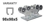
Pivoting all-metal carriage for C-profile 98 × 98 × 5 mm; the product specifies an opening width of up to 8.5 m.
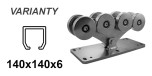
System carriage with eight metal wheels for large C-profile 140 × 140 × 6 mm.
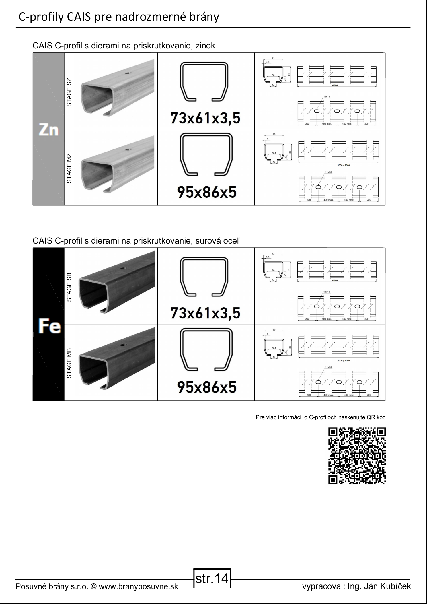
The source drawings use an 80 × 80 × 5 mm profile. More robust systems are also available for heavier loads; choose the specific size only after checking the weight, infill, wind load and compatible carriages.
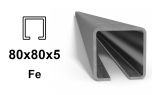
Size used in the source drawings for openings from 7.0 to 10.0 m.
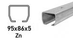
Profile with pre-drilled holes for bolting; a more robust system option.
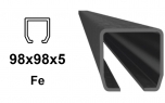
Larger steel profile for individually sized assemblies.
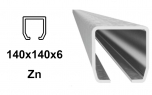
The largest profile shown, for large structures that have been assessed individually.
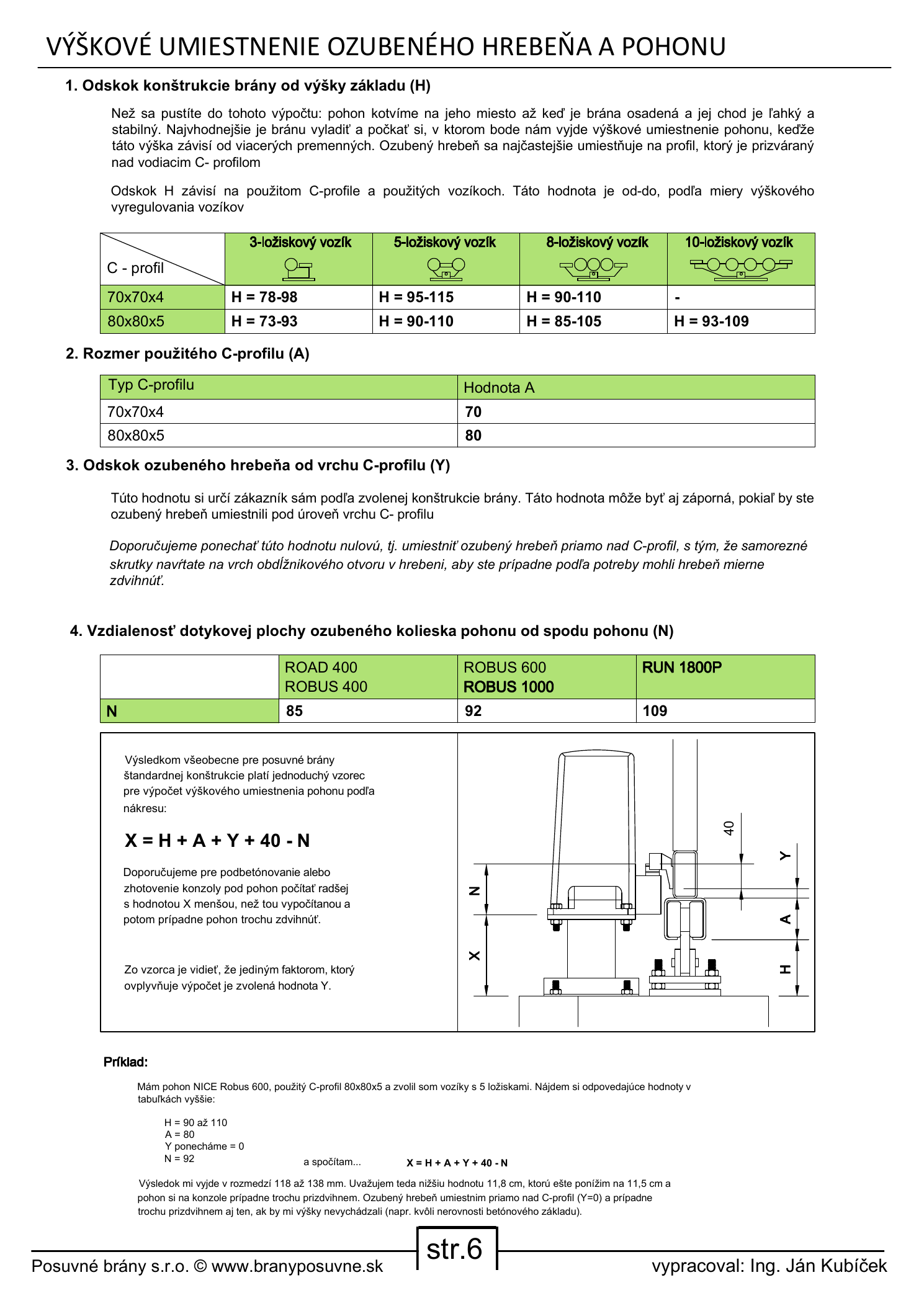
The height X of the drive mounting plate depends on carriage height H, C-profile height A, the required clearance Y beneath the rack, and dimension N of the specific drive.
| Component | Variant | Dimension |
|---|---|---|
| A – C-profile height | 70 × 70 × 4 mm | 70 mm |
| 80 × 80 × 5 mm | 80 mm | |
| N – drive pinion height | ROAD 400 / ROBUS 400 | 85 mm |
| ROBUS 600 / ROBUS 1000 | 92 mm | |
| RUN 1800P | 109 mm |
RBS600 and RBS800 are part of the new generation of NICE ROBUS drives. The older RB1000 and RUN1800 drives have their own wiring diagrams.
NICE ROBUS RBS600 assembly (D) | NICE ROBUS RBS800 assembly (D)
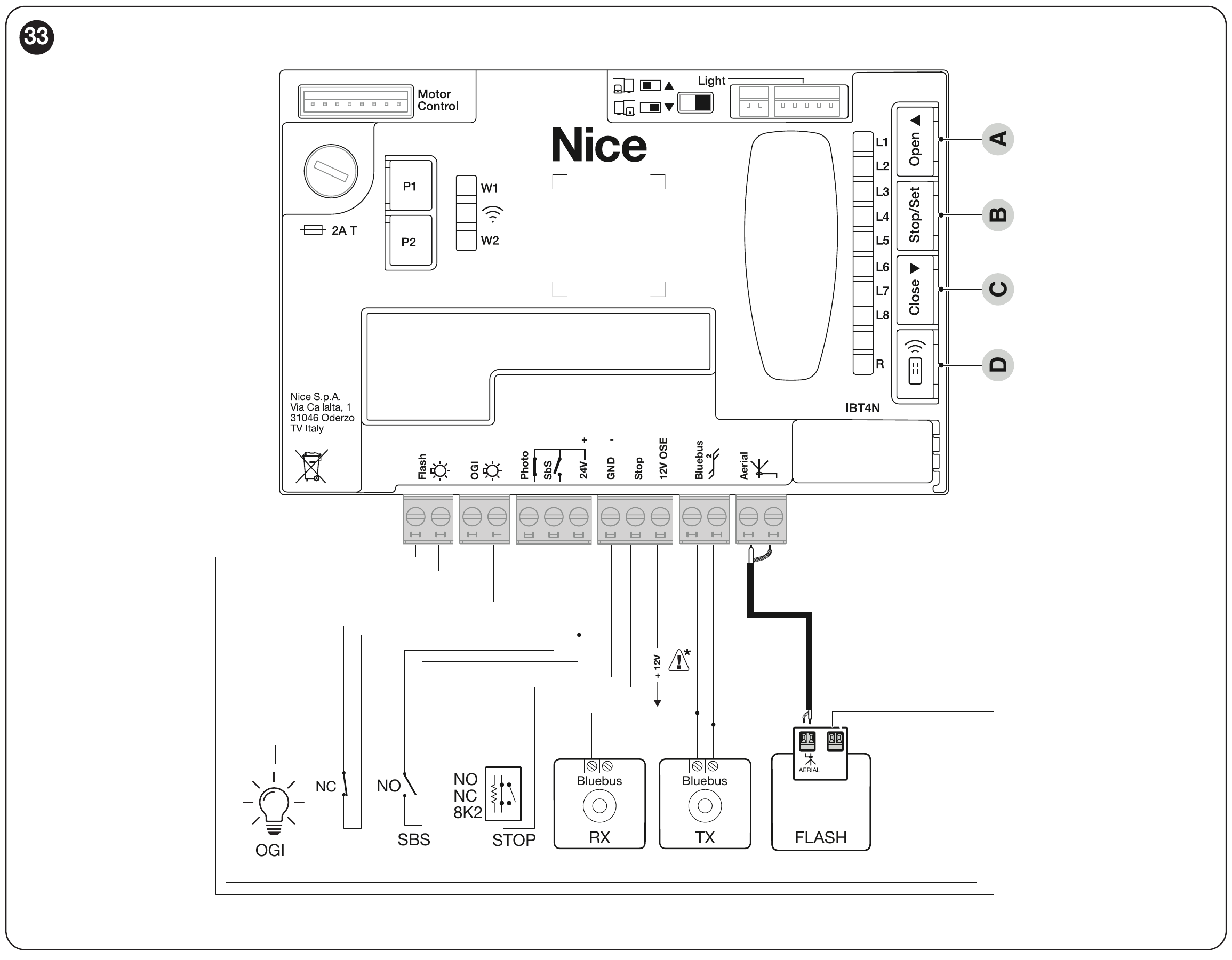
NICE ROBUS RB1000 assembly (D)
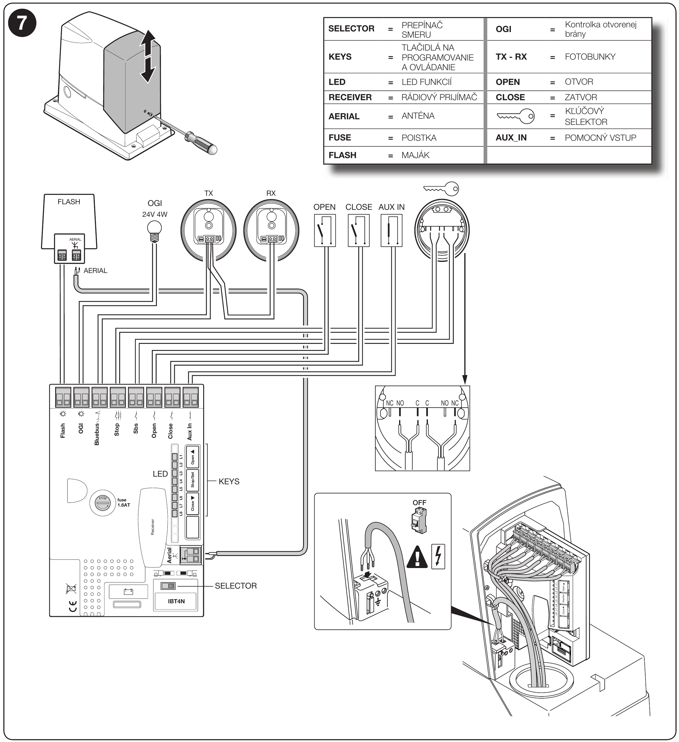
The NICE RUN1800 uses a 230 V AC electric motor, while the ROBUS RBS600/RBS800 and the older RB1000 have a 24 V DC motor. This is the main difference in the motor’s power supply. Both types of operator are connected to the 230 V mains supply.
RUA1 control unit has similar basic functions to the ROBUS. It supports automatic closing, partial opening and connection of BlueBUS photocells. However, the terminal layout and specific wiring differ.
400 × 255 × 390 mm (length × width × height) according to the manufacturer’s technical table.
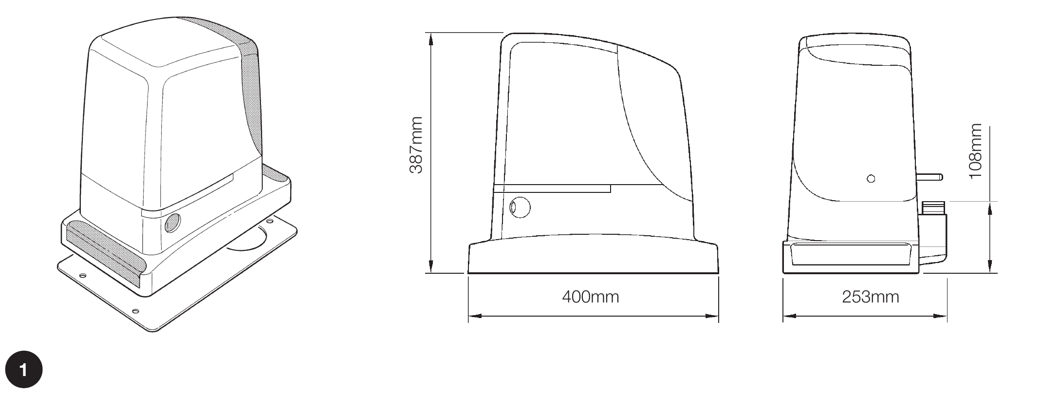
The dimension drawing lists 400 × 253 × 387 mm, while the technical table in the same manual lists 400 × 255 × 390 mm.
Dimension drawing in the manual (PDF, page 4) | Technical data (PDF, page 24)
The RUN1800 wiring diagram shows the original LUCYB, MOFB and MOSE accessories. It does not show the current kit.
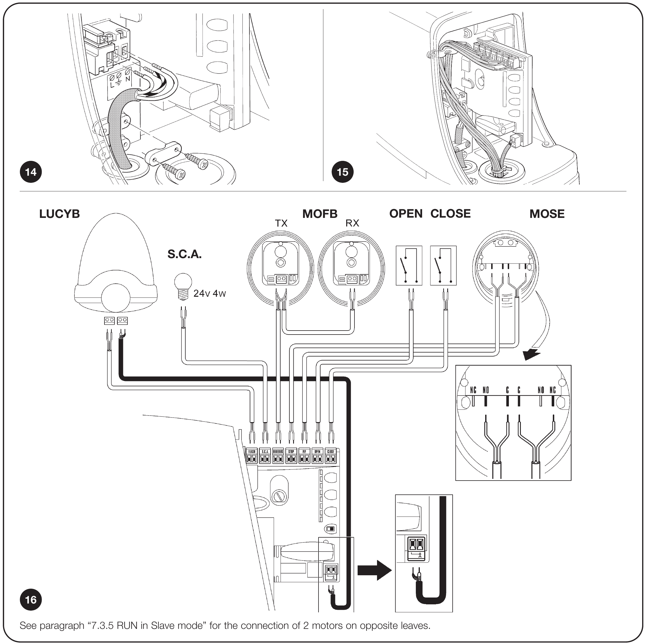
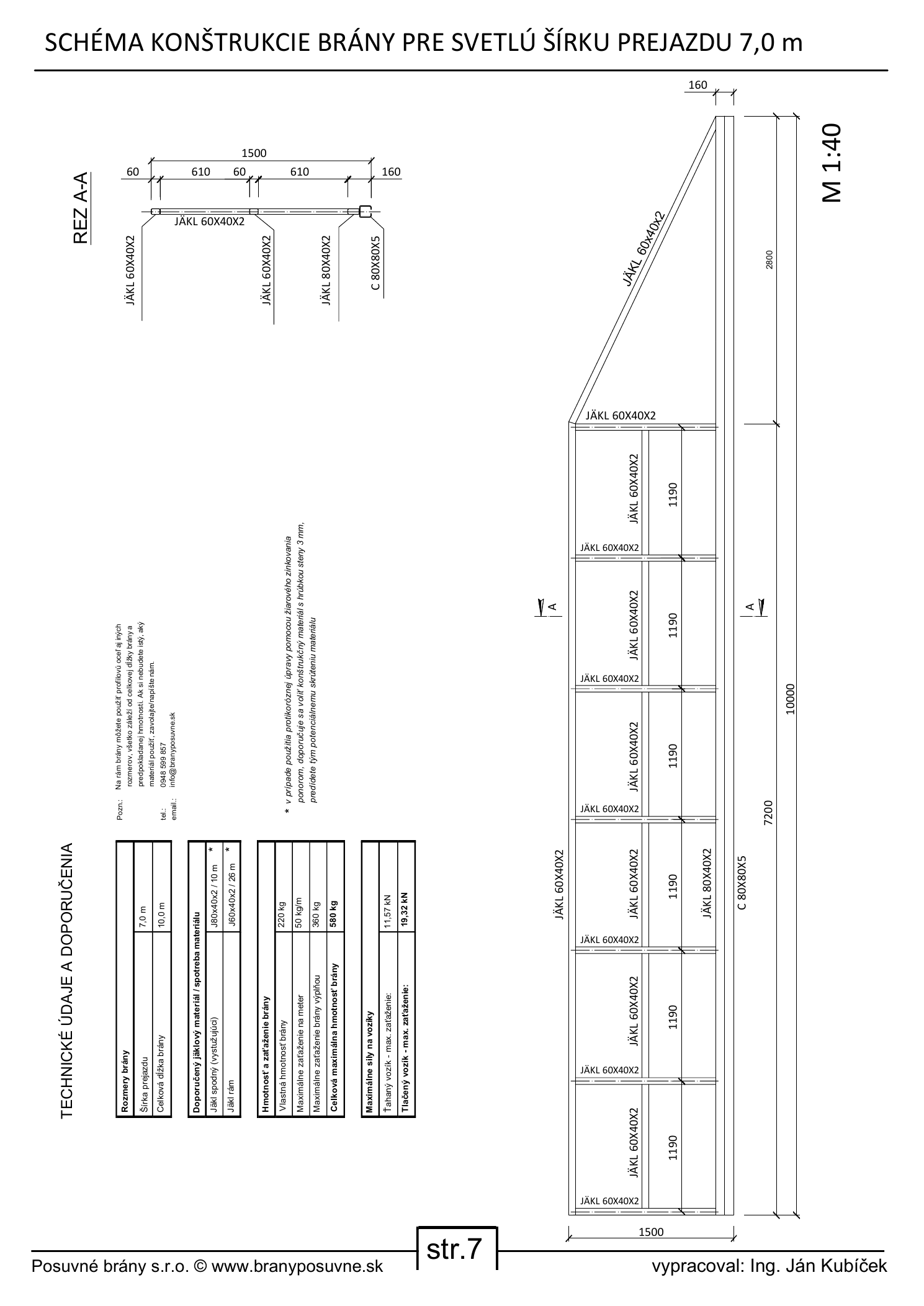
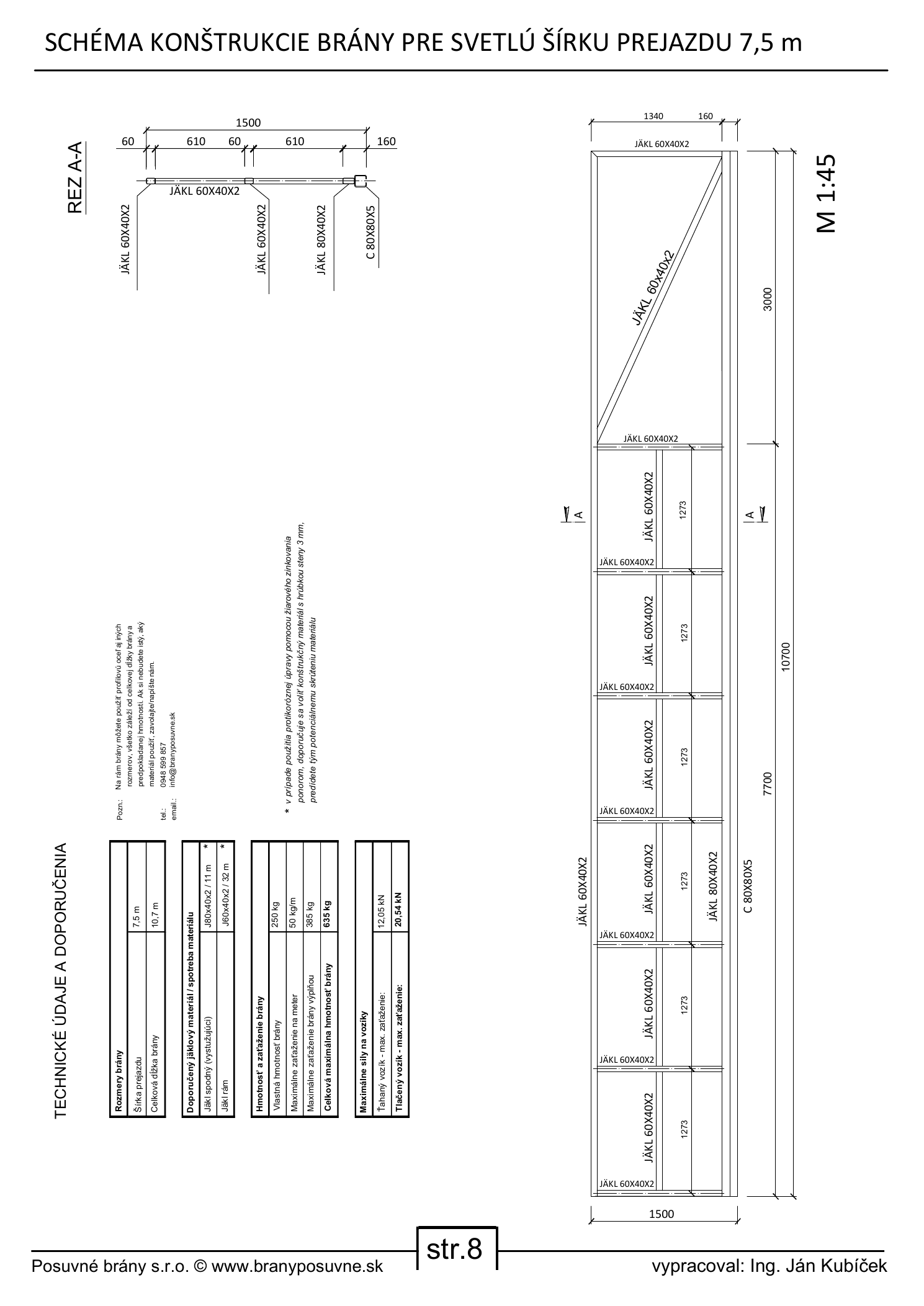
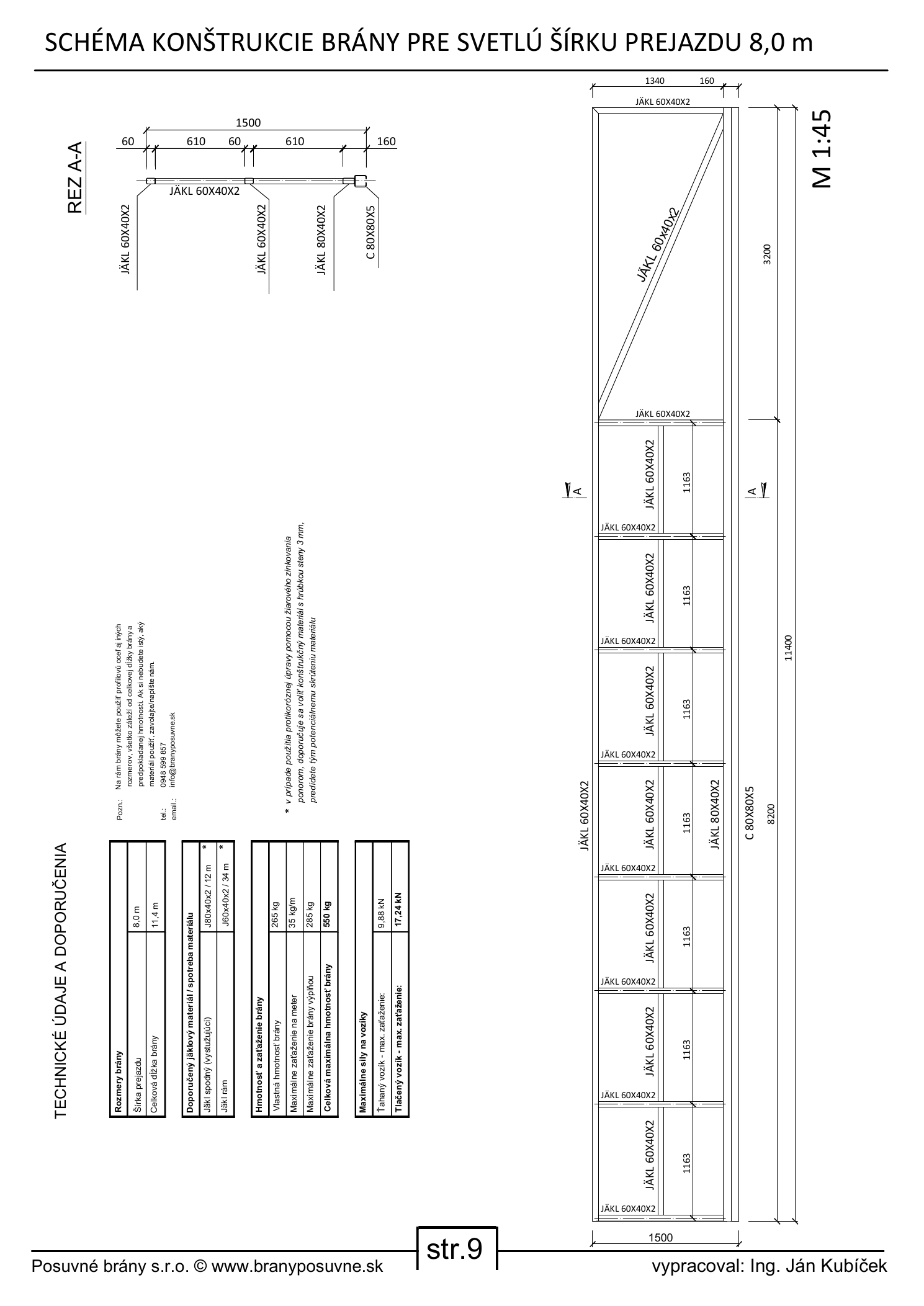
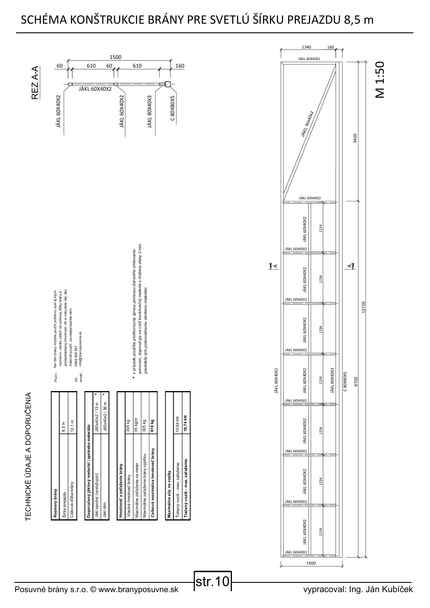
Applies to the drawings below. The dimensions, net weight and maximum loads apply to the specific assemblies shown in these drawings.
| Clear opening | Overall gate length | Gate dead weight | Max. load per metre | Max. infill weight |
|---|---|---|---|---|
| 7.0 m | 10.0 m | 220 kg | 50 kg/m | 360 kg |
| 7.5 m | 10.7 m | 250 kg | 50 kg/m | 385 kg |
| 8.0 m | 11.4 m | 265 kg | 35 kg/m | 285 kg |
| 8.5 m | 12.1 m | 305 kg | 35 kg/m | 305 kg |
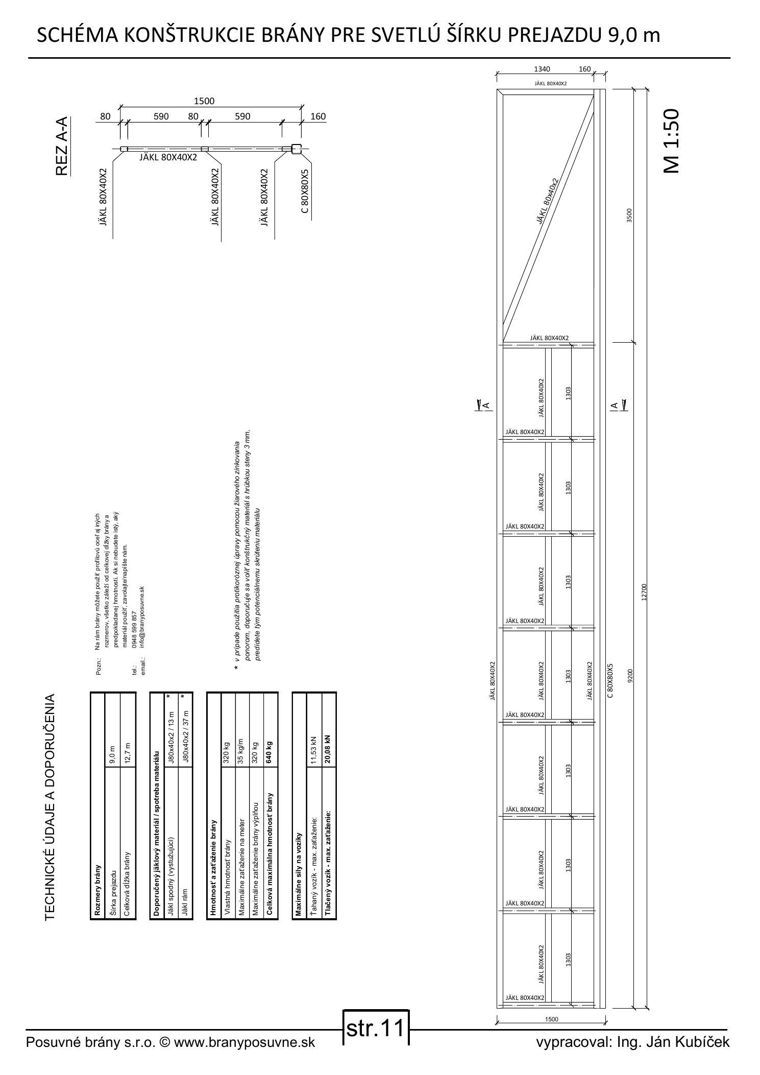
| 9.0 m | 12.7 m | 320 kg | 35 kg/m | 320 kg |
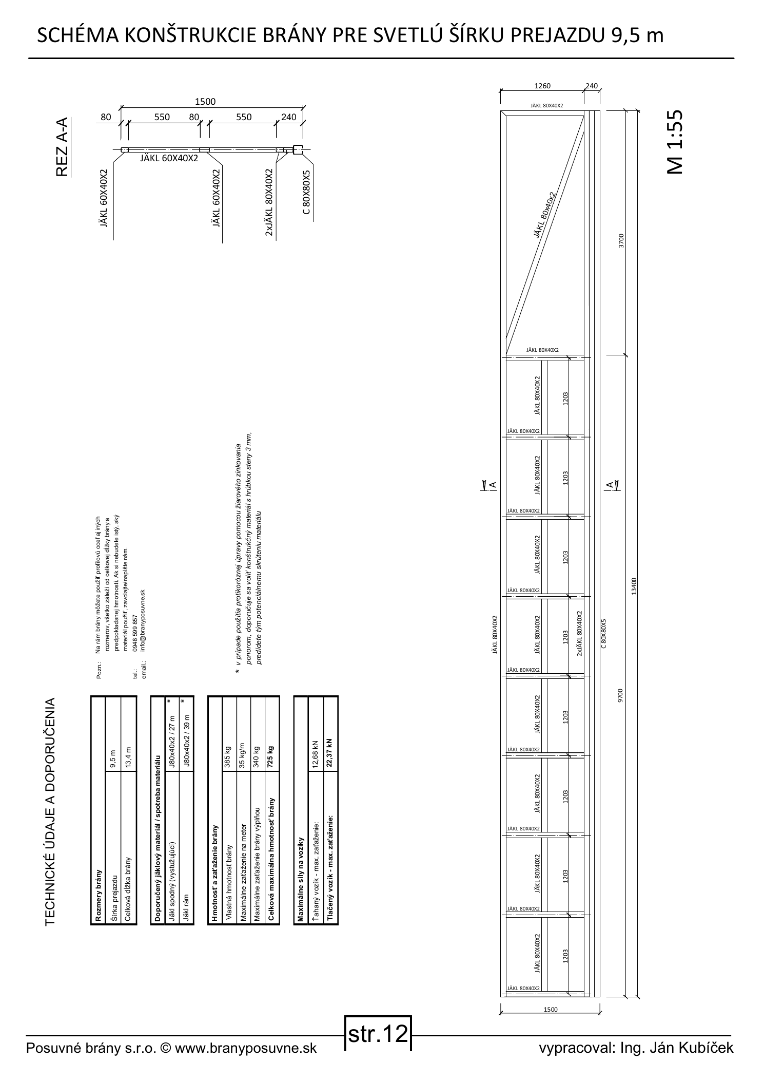
| 9.5 m | 13.4 m | 385 kg | 35 kg/m | 340 kg |
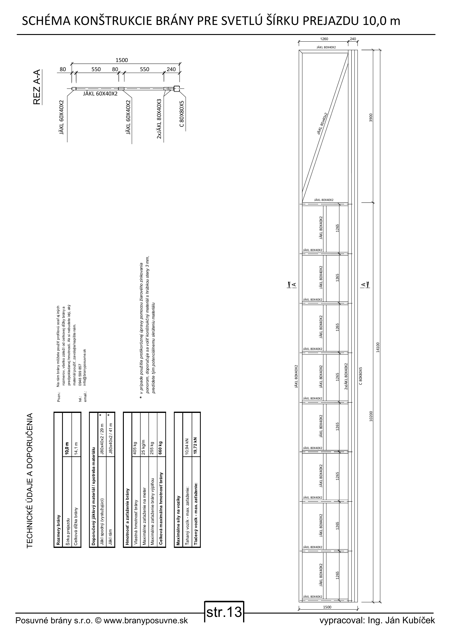
| 10.0 m | 14.1 m | 405 kg | 25 kg/m | 255 kg |
For the same external dimensions, a box-section tube with a thicker wall weighs more. The following table compares the weight of the frame and bottom reinforcement box-section tubes alone based on the material quantities shown in the drawings. It excludes the 80 × 80 × 5 mm supporting C-profile, infill, fittings and other parts, so these figures are not the net weight of the complete gate shown in the table above.
| Clear opening | Gate length | 2 mm wall | 3 mm wall | 4 mm wall |
|---|---|---|---|---|
| 7.0 m | 10.0 m | 111.8 kg | 162.4 kg | 208.8 kg |
| 7.5 m | 10.7 m | 132.9 kg | 193.1 kg | 248.2 kg |
| 8.0 m | 11.4 m | 142.3 kg | 206.8 kg | 265.8 kg |
| 8.5 m | 12.1 m | 151.8 kg | 220.5 kg | 283.4 kg |
| 9.0 m | 12.7 m | 178.0 kg | 259.5 kg | 335.5 kg |
| 9.5 m | 13.4 m | 235.0 kg | 342.5 kg | 442.9 kg |
| 10.0 m | 14.1 m | 249.2 kg | 363.3 kg | 469.7 kg |
How to choose the frame: Design the gate to be as light as possible while still providing sufficient strength and rigidity for the chosen infill and wind load. Using box-section tubes of a different size or wall thickness will change the frame’s weight and performance. A heavier frame also puts more load on the C-profile and guide rollers. Therefore, the permissible infill weight cannot be increased simply in proportion to the wall thickness.
The maximum load and infill weight values in the first table do not automatically apply to versions with 3 and 4 mm walls. This comparison calculates the material weight, not a new gate load capacity.
The outer dimensions of the box sections and the material quantities remain the same in all three columns. Only the wall thickness changes. The quantities are taken from the drawing's bill of materials, not from an exact cutting plan. Offcuts, welds, surface finish and the tolerances of the supplied profiles also affect the weight of the finished frame.
| Clear opening | 60 × 40 mm box section | 80 × 40 mm box section |
|---|---|---|
| 7.0 m | 26 m | 10 m |
| 7.5 m | 32 m | 11 m |
| 8.0 m | 34 m | 12 m |
| 8.5 m | 36 m | 13 m |
| 9.0 m | 0 m | 50 m |
| 9.5 m | 0 m | 66 m |
| 10.0 m | 0 m | 70 m |
For a clear opening of 9.0 m, the total length of 80 × 40 mm box section used is 13 + 37 m; for 9.5 m, it is 27 + 39 m; and for 10.0 m, it is 29 + 41 m. The total also includes the lower reinforcement shown in the drawing.
| External dimensions | 2 mm wall | 3 mm wall | 4 mm wall |
|---|---|---|---|
| 60 × 40 mm | 2.93 kg/m | 4.25 kg/m | 5.45 kg/m |
| 80 × 40 mm | 3.56 kg/m | 5.19 kg/m | 6.71 kg/m |
Calculation: weight = length of 60 × 40 box section × its weight per metre + length of 80 × 40 box section × its weight per metre. For example, for a 7.0 m clear opening and a 3 mm wall: 26 × 4.25 + 10 × 5.19 = 162.4 kg of box sections.
The linear weights are from the SSAB dimension table, verified on 11. 9. 2026. They are reference values for comparing weights, not confirmation by the manufacturer or of the material grade used in the drawings.
Discrepancies in the drawings: For clear openings of 8.5 m and 10.0 m, the lower box section is labelled differently in the cross-section than in the bill of materials: the section shows a 3 mm wall instead of 2 mm. For 9.5 m and 10.0 m openings, the frame cross-section shows 60 × 40 mm, while the elevation and bill of materials specify 80 × 40 mm. The comparison above explicitly uses the bill of materials. This does not correct the original drawings or their load ratings.
Each preview links to the full-resolution image. The summary table above also lists the key dimensions and weights as text; the drawings retain the frame layout, sections, dimensions and carriage load ratings.
7.0 m clear opening
Overall length 10,000 mm, frame 7,200 mm, counterbalance 2,800 mm, frame height 1,500 mm, 80 × 80 × 5 mm C-track.
7.5 m clear opening
Overall length 10,700 mm, frame 7,700 mm, counterbalance 3,000 mm, frame height 1,500 mm, 80 × 80 × 5 mm C-track.
8.0 m clear opening
Overall length 11,400 mm, frame 8,200 mm, counterbalance 3,200 mm, frame height 1,500 mm, 80 × 80 × 5 mm C-track.
8.5 m clear opening
Overall length 12,100 mm, frame 8,700 mm, counterbalance 3,400 mm, frame height 1,500 mm, 80 × 80 × 5 mm C-track.
9.0 m clear opening
Overall length 12,700 mm, frame 9,200 mm, counterbalance 3,500 mm, frame height 1,500 mm, 80 × 80 × 5 mm C-track.
9.5 m clear opening
Overall length 13,400 mm, frame 9,700 mm, counterbalance 3,700 mm, frame height 1,500 mm, 80 × 80 × 5 mm C-track.
10.0 m clear opening
Overall length 14,100 mm, frame 10,200 mm, counterbalance 3,900 mm, frame height 1,500 mm, 80 × 80 × 5 mm C-track.
Contact us. For gates over 6.5 m, we recommend checking the component selection before ordering and pouring the concrete.
Component kits for cantilever gates
CAIS components for large gates
If a large cantilever gate won't fit on your property, consider another solution. A telescopic gate or other options could be a suitable compromise and help solve the lack of space on your property.
Prepared by Eng. Ján Kubíček.
Last updated: 16 September 2026.