Space
- clear opening width (ŠP),
- the side and direction in which the gate opens,
- clearance for the entire gate, including the counterbalance,
- ground levels along the entire travel path.
Technical guide · DIY construction · cantilever gate
From measuring the opening and pouring the concrete foundation to wiring, carriages, guide system and drive, with a dimensions overview and technical drawings for openings from 2.5 to 6.5 m.
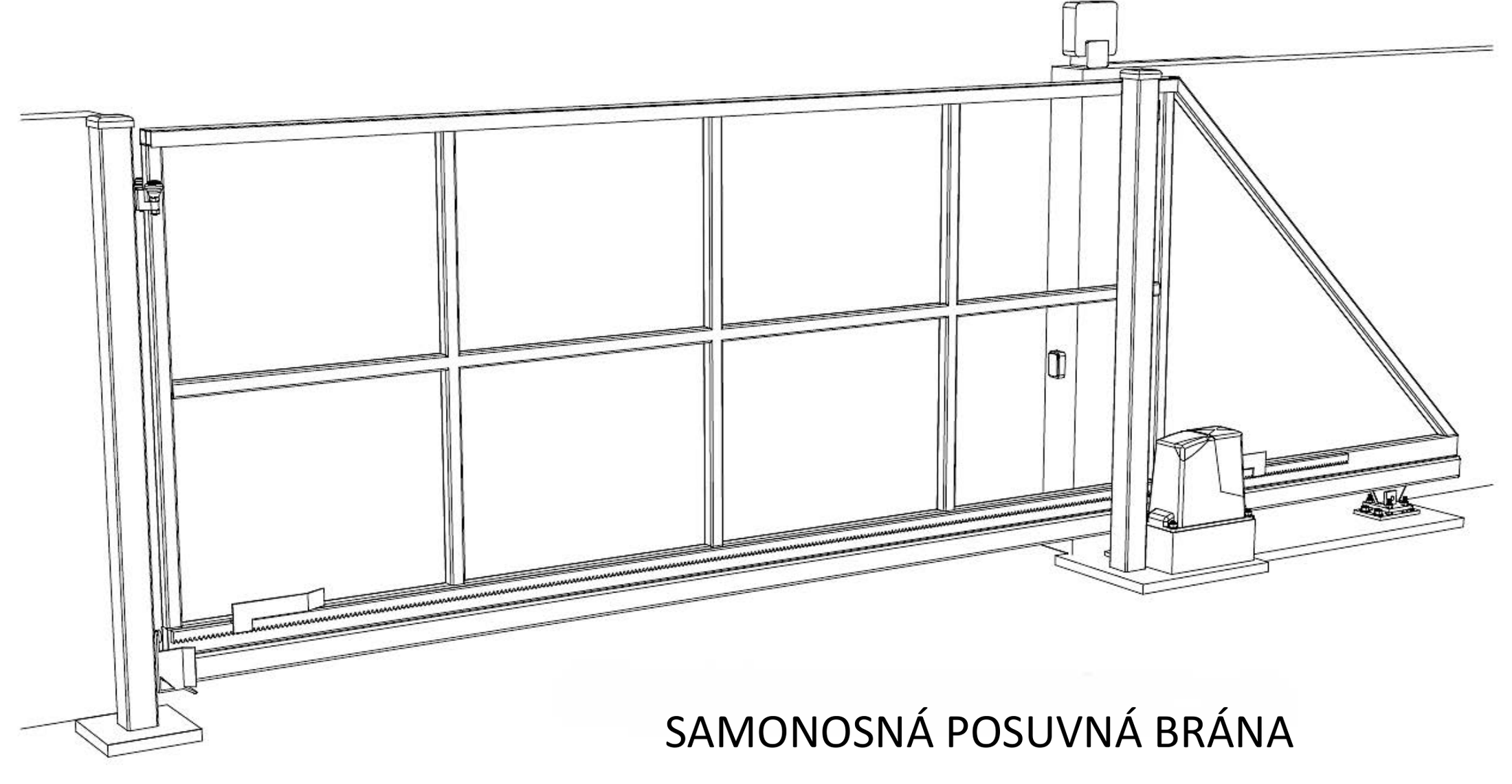
A cantilever gate moves above ground level without a track across the opening. The gate leaf is supported by carriages anchored in a concrete foundation and a load-bearing C-channel welded to the bottom of the frame. The design must coordinate the overall gate-leaf length, counterbalance, profile, carriages, infill, guide system, foundation and, if required, drive.
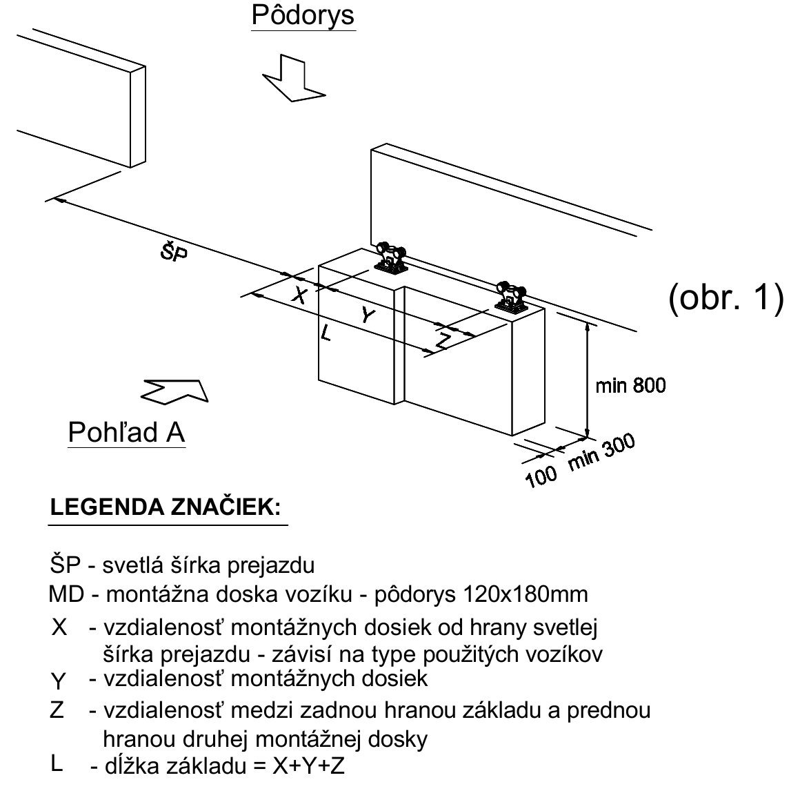
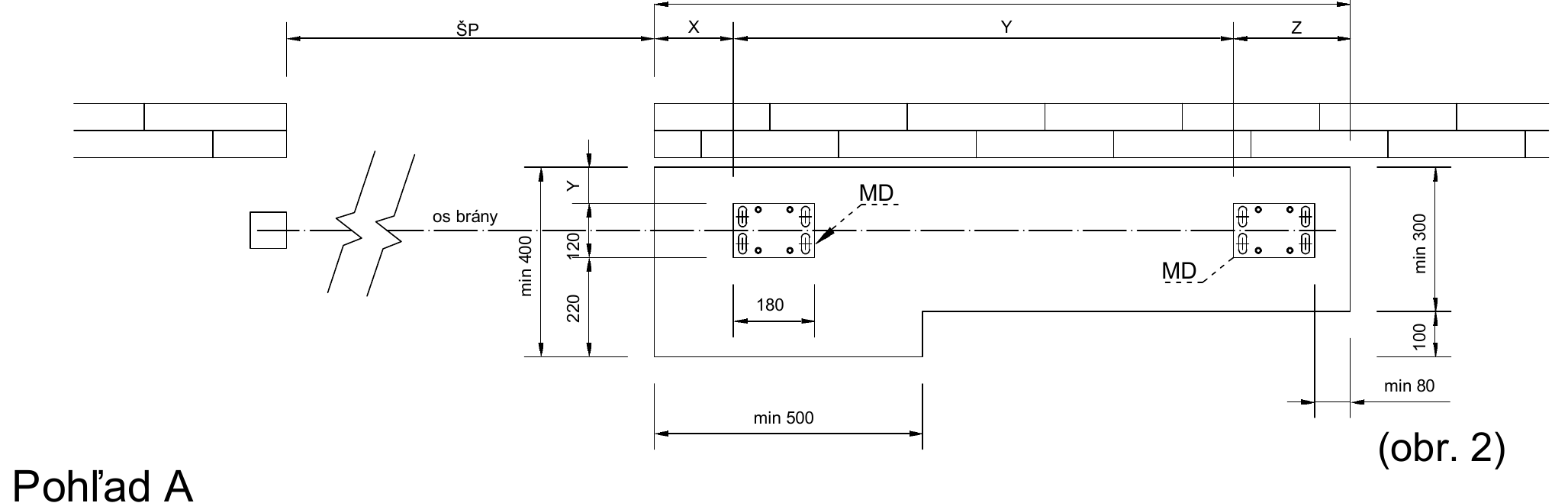
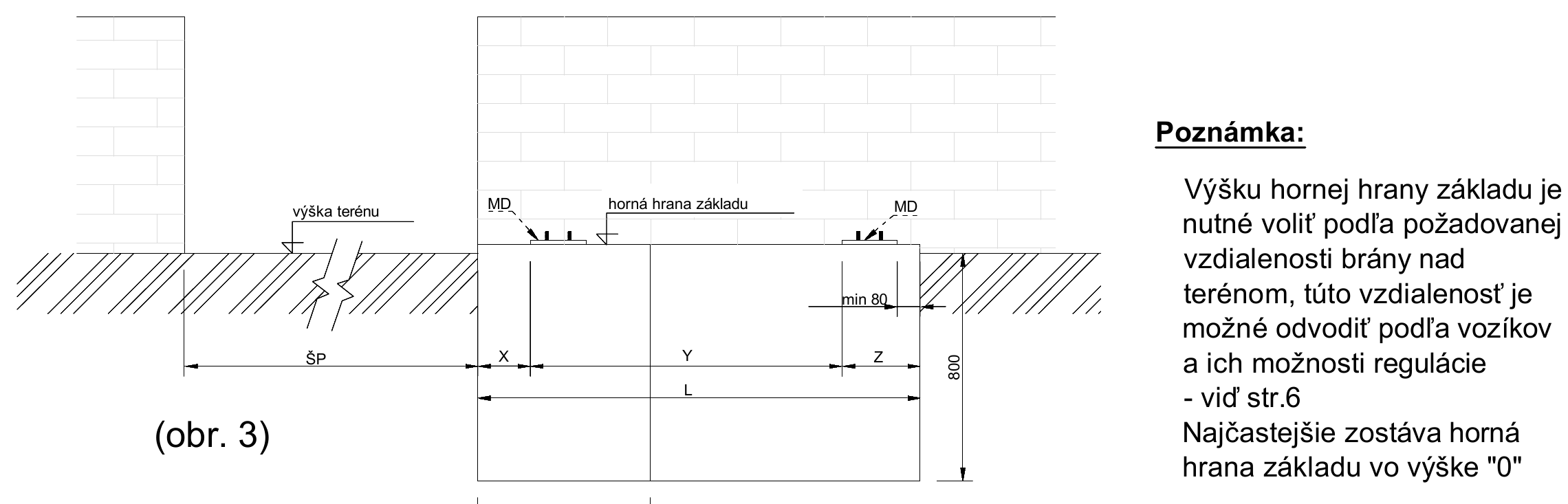
The foundation length is calculated in the source as L = X + Y + Z. Dimension X is 160 mm for carriages with 3 or 5 rollers and 240 mm for carriages with 8 rollers. The foundation should be at least 800 mm deep; its final dimensions must be confirmed by a design based on the soil, frost conditions and local requirements.
| Clear opening width | Y | Z | L |
|---|---|---|---|
| 2,500 mm | 750 mm | 290 mm | 1,200 mm |
| 3,000 mm | 950 mm | 290 mm | 1,400 mm |
| 3,500 mm | 1,150 mm | 290 mm | 1,600 mm |
| 4,000 mm | 1,300 mm | 340 mm | 1,800 mm |
| 4,500 mm – short | 1,050 mm | 290 mm | 1,500 mm |
| 4,500 mm – full | 1,500 mm | 340 mm | 2,000 mm |
| 5,000 mm | 1,700 mm | 340 mm | 2,200 mm |
| 5,500 mm | 1,850 mm | 290 mm | 2,300 mm |
| 6,000 mm | 2,050 mm | 290 mm | 2,500 mm |
| 6,500 mm | 1,950 mm | 290 mm | 2,400 mm |
| Clear opening width | Y | Z | L |
|---|---|---|---|
| 2,500 mm | 650 mm | 310 mm | 1,200 mm |
| 3,000 mm | 900 mm | 260 mm | 1,400 mm |
| 3,500 mm | 1,100 mm | 260 mm | 1,600 mm |
| 4,000 mm | 1,250 mm | 310 mm | 1,800 mm |
| 4,500 mm – short | 900 mm | 260 mm | 1,400 mm |
| 4,500 mm – full | 1,350 mm | 310 mm | 1 900 mm |
| 5 000 mm | 1 550 mm | 310 mm | 2 100 mm |
| 5 500 mm | 1 750 mm | 310 mm | 2 300 mm |
| 6 000 mm | 1 950 mm | 310 mm | 2 500 mm |
| 6 500 mm | 1 900 mm | 260 mm | 2 400 mm |
Run the conduits to the operator, both photocells and the warning light before pouring the concrete. Allow for a cable exit approximately 300 mm from the edge at the operator, depending on the chosen orientation; in the source, the photocell on the right-hand post is approximately 180 mm above the corresponding exit.
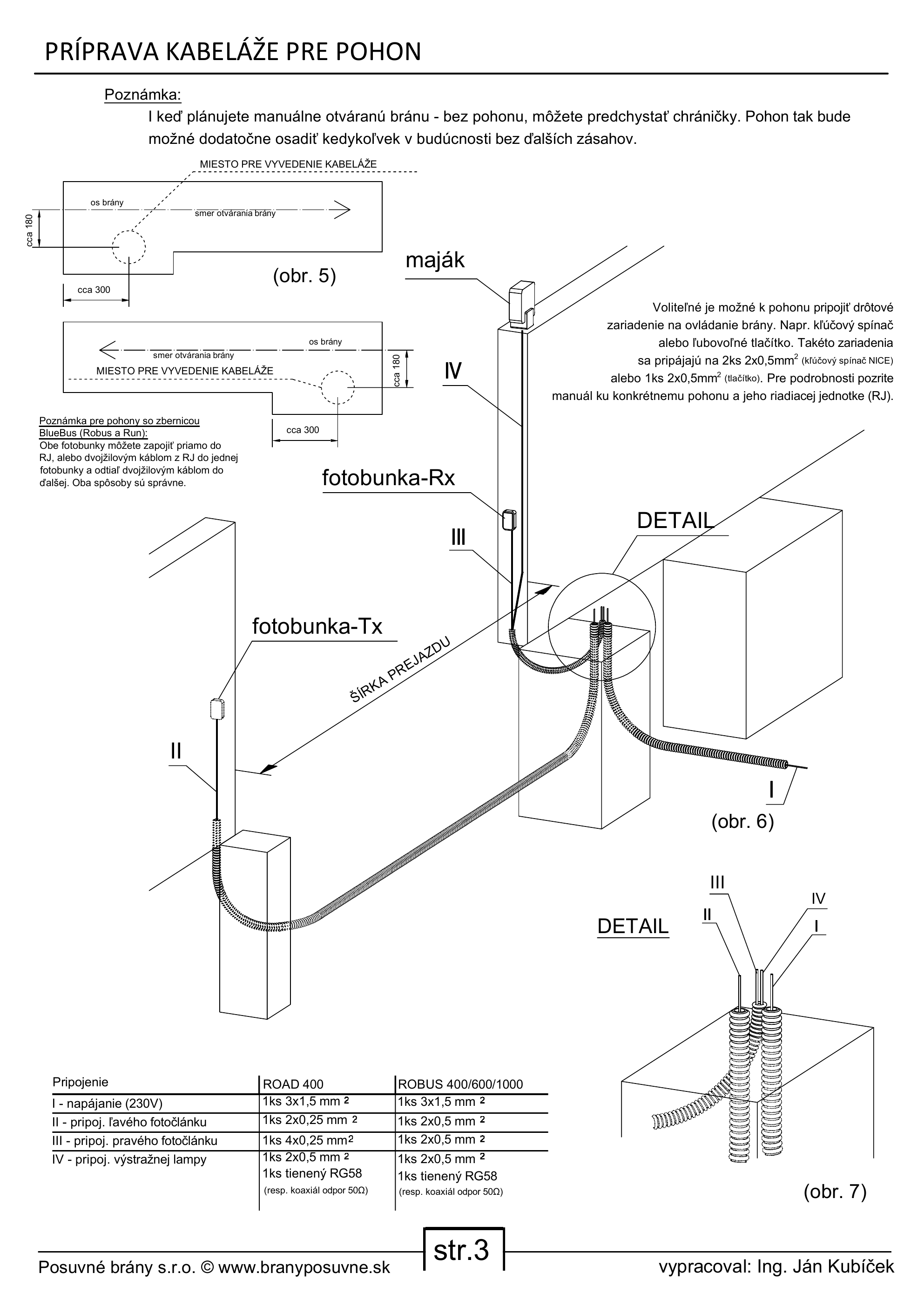
| Route | Function | Nice Road RD400 | Nice Robus RB 400/600/1000 – older generation |
|---|---|---|---|
| I | 230 V operator power supply | 1 × 3 × 1.5 mm² | 1 × 3 × 1.5 mm² |
| II | Left photocell, transmitter Tx | 1 × 2 × 0.25 mm² | 1 × 2 × 0.5 mm² |
| III | Right photocell, receiver Rx | 1 × 4 × 0.25 mm² | 1 × 2 × 0.5 mm² |
| IV | Warning light and antenna | 1 × 2 × 0.5 mm² + shielded RG58, 50 Ω | 1 × 2 × 0.5 mm² + shielded RG58, 50 Ω |
According to the source, an optional key switch requires 2 × 2 × 0.5 mm² cable; a simple push button requires 1 × 2 × 0.5 mm² cable. With a BlueBUS system, the photocells can be wired individually to the control unit or daisy-chained, if permitted by the specific control unit and its manual.
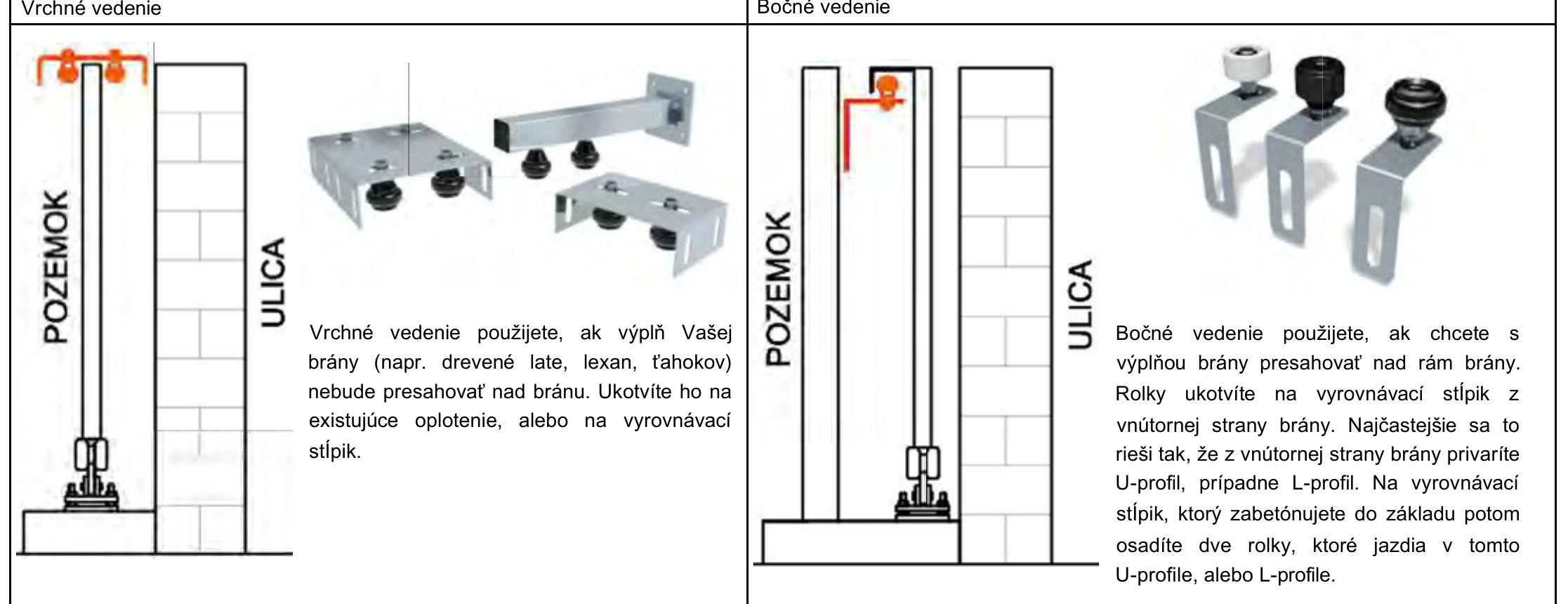
The guide rollers run along the top of the frame. The structure must have a rigid post or lintel in the correct position and must not pinch the gate.
The side guide bracket guides the frame from the side. Check the clearance, post rigidity and roller adjustment, and make sure the infill and welds do not obstruct the gate’s path.
Below are typical choices for the range covered by this manual. Choose the final carriage according to the C-profile, opening width, weight, infill and gate construction.
For shorter openings up to 3 m. For C-profile 70 or 80; mounting plate 180 × 120 mm.
A typical choice for openings 3 to 5 m wide. Option for C-profile 70 or 80; mounting plate 180 × 120 mm.
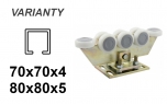
The product is designed for openings 5 to 7.5 m wide; this manual covers the 5 to 6.5 m variants. For C-profile 70 or 80.
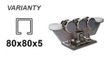
All-steel option for C-profile 80. The product is designed for openings 5 to 7.5 m wide; this manual covers the 5 to 6.5 m variants.
The drawings for openings 2.5 to 4.0 m wide use a 70 × 70 × 4 mm C-profile; the drawings for openings 4.5 to 6.5 m wide use an 80 × 80 × 5 mm profile. Select the material and always check the final load together with the carriages and gate infill.
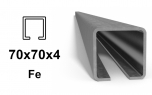
Size used in the drawings for openings 2.5 to 4.0 m wide. Black steel, lengths 1 to 6 m.
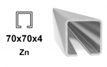
Galvanised version of the size used in the drawings for openings 2.5 to 4.0 m wide.
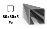
Size used in the drawings for openings 4.5 to 6.5 m wide. Black steel, lengths 1 to 6 m.
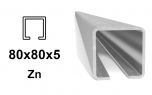
Galvanised version of the size used in the drawings for openings 4.5 to 6.5 m wide.
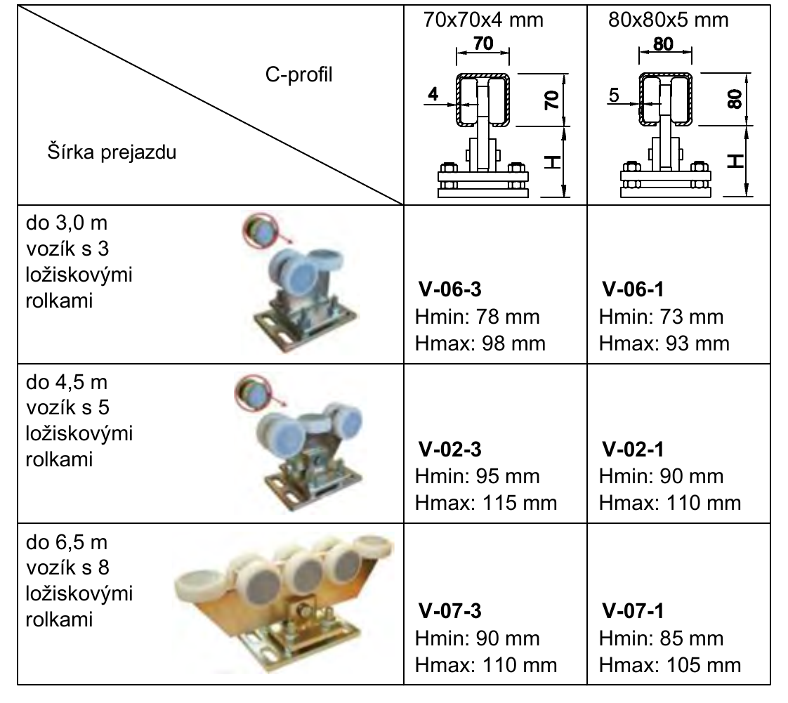
| Trolley | 70 × 70 × 4 mm | 80 × 80 × 5 mm |
|---|---|---|
| 3 rollers | V-06-3 · 78 to 98 mm | V-06-1 · 73 to 93 mm |
| 5 rollers | V-02-3 · 95 to 115 mm | V-02-1 · 90 to 110 mm |
| 8 rollers | V-07-3 · 90 to 110 mm | V-07-1 · 85 to 105 mm |
| 10 rollers | — | 93 to 109 mm |
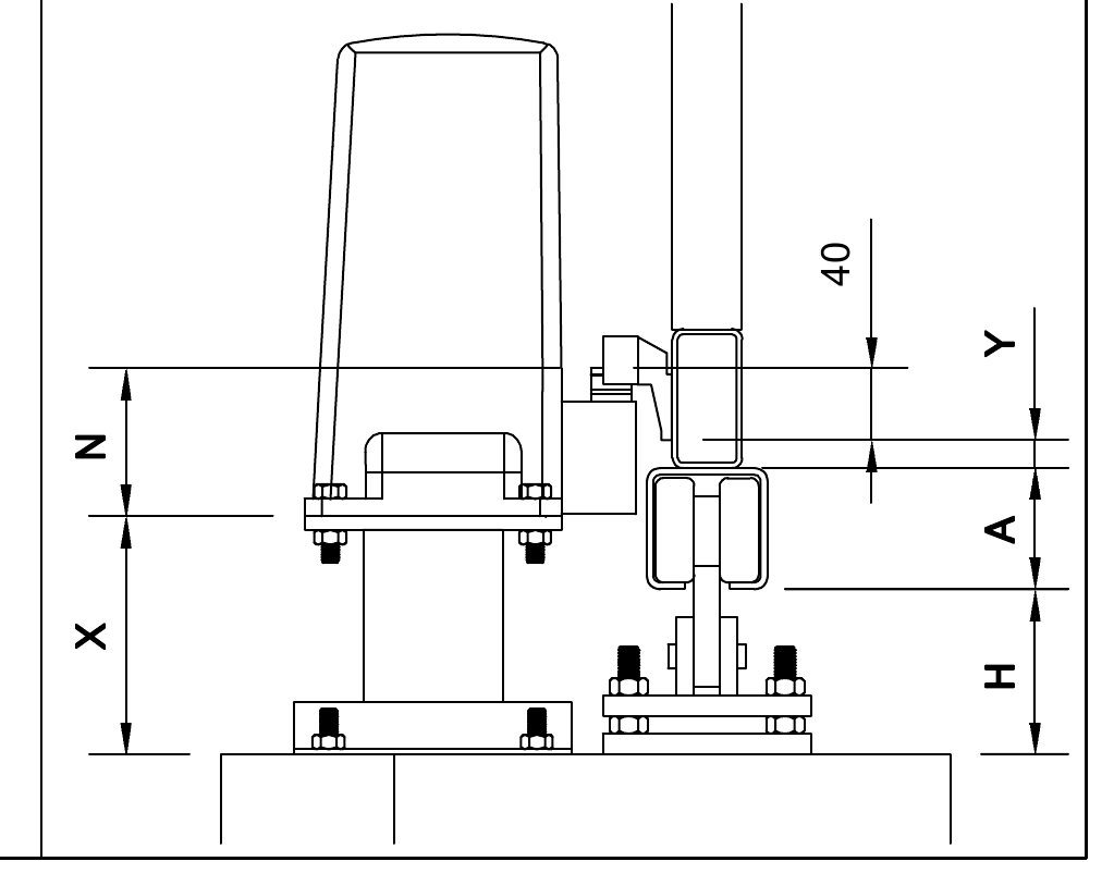
Choose H within the adjustment range so that the gate remains above the highest point of the ground while maintaining the correct position of the drive, rack, end-stop components and guide.
The source uses the following designations: H = trolley height, A = C-section height, Y = required gate clearance above the ground, N = drive construction height. The position of the drive mounting plate X is determined by the following formula:
The source specifies N = 85 mm for Road 400 and Robus 400, N = 92 mm for Robus 600/1000, and N = 109 mm for Run 1800P. These values apply to specific older models; for a different or newer drive, measure N using its installation drawing.
Example from the source: Robus 600, an 80 mm C-section, 5-roller trolleys with H = 90 to 110 mm, clearance Y = 0 and N = 92 mm give X = 118 to 138 mm. The source then selects a mounting height of 115 mm; therefore, before use, physically check the position against the specific trolley, rack and drive.
The excerpt shows the basic mains cable connection and the location of the terminals in the Road RD400 drive. The original PDF also contains another image labelled for a different control unit; it has been deliberately omitted to avoid mixing two incompatible diagrams.
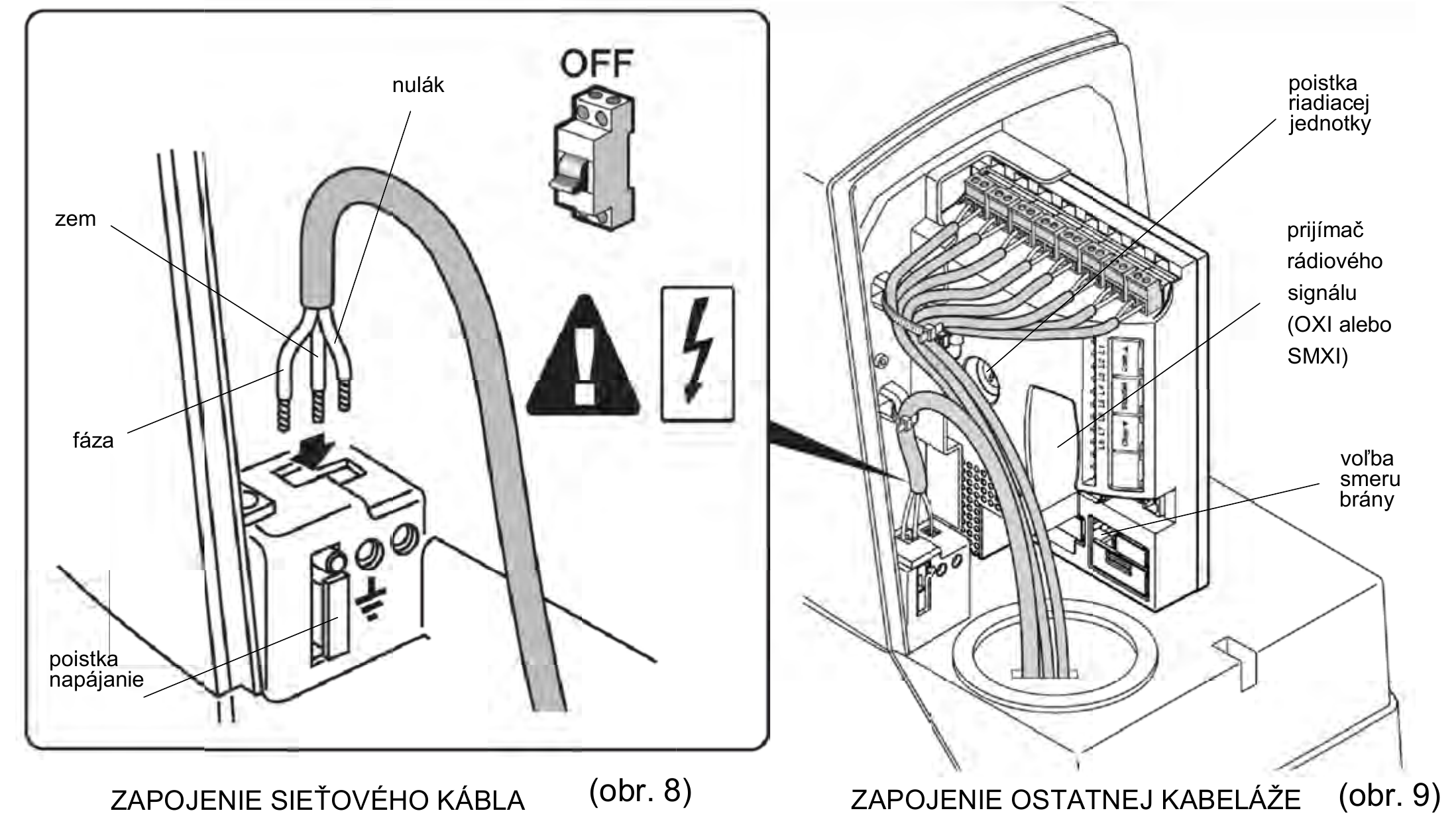
The diagrams are reproduced from page 5 of the v5 manual for sliding gates. The original wiring, labels and enlarged terminal-block detail have been retained; the diagrams have not been redrawn.
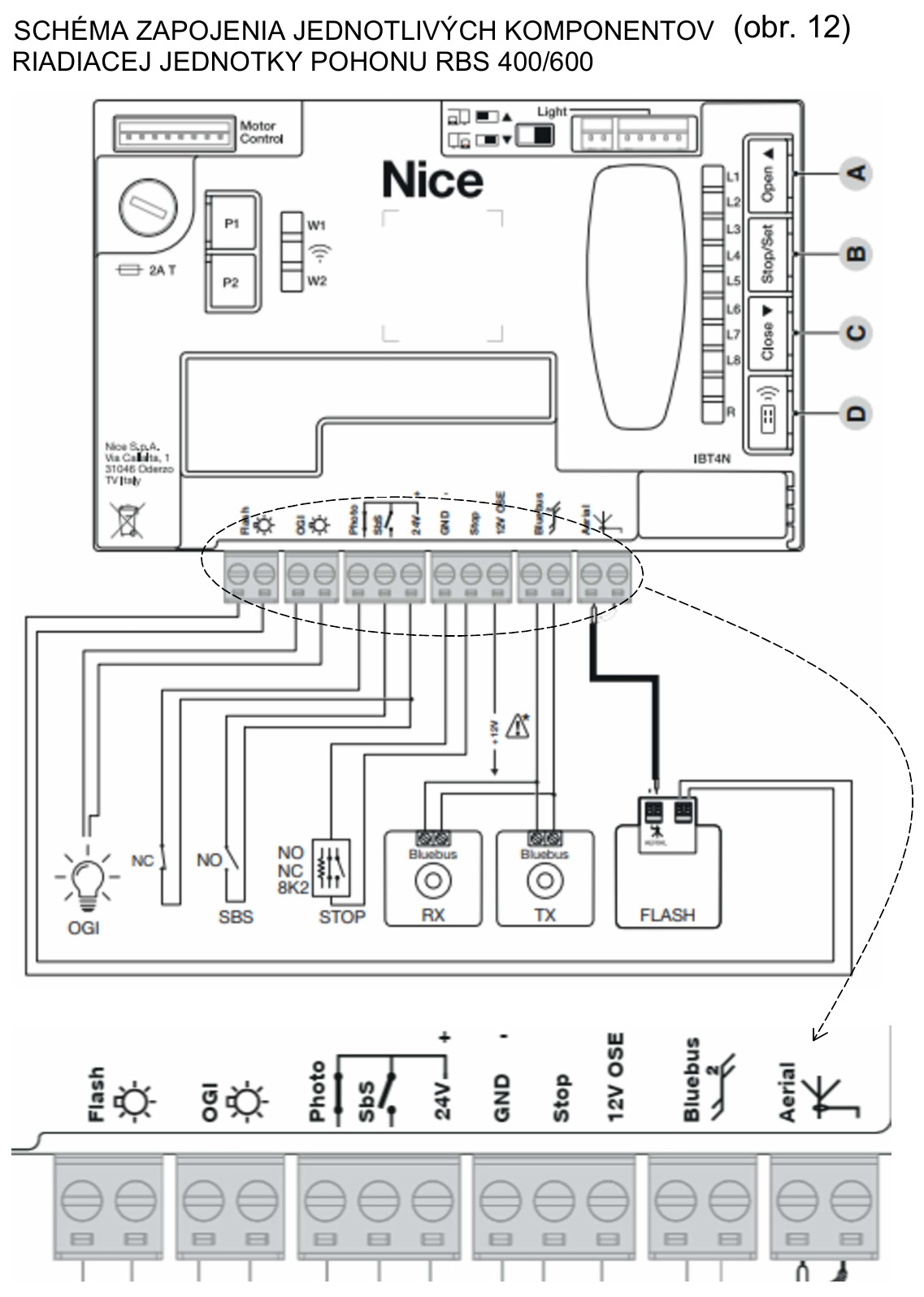
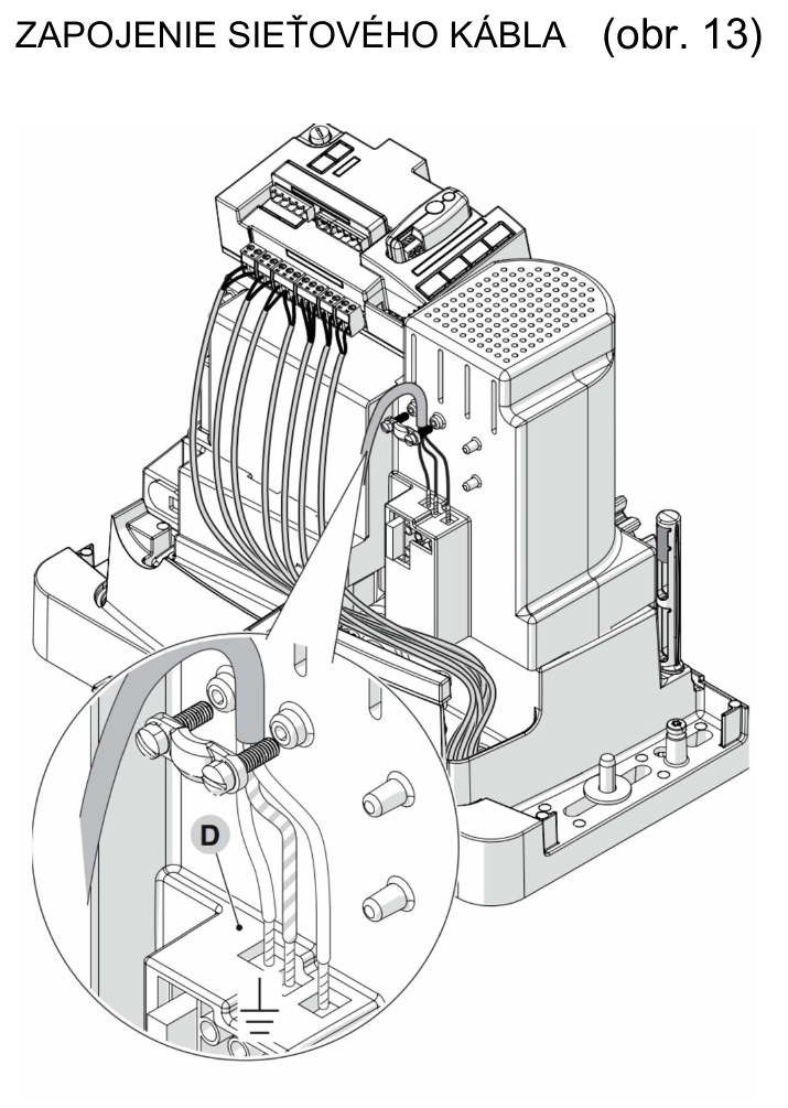
NICE RBS400/600/600HS installation manual – wiring diagrams and descriptions.
Products: NICE Robus RBS400 and NICE Robus RBS600.
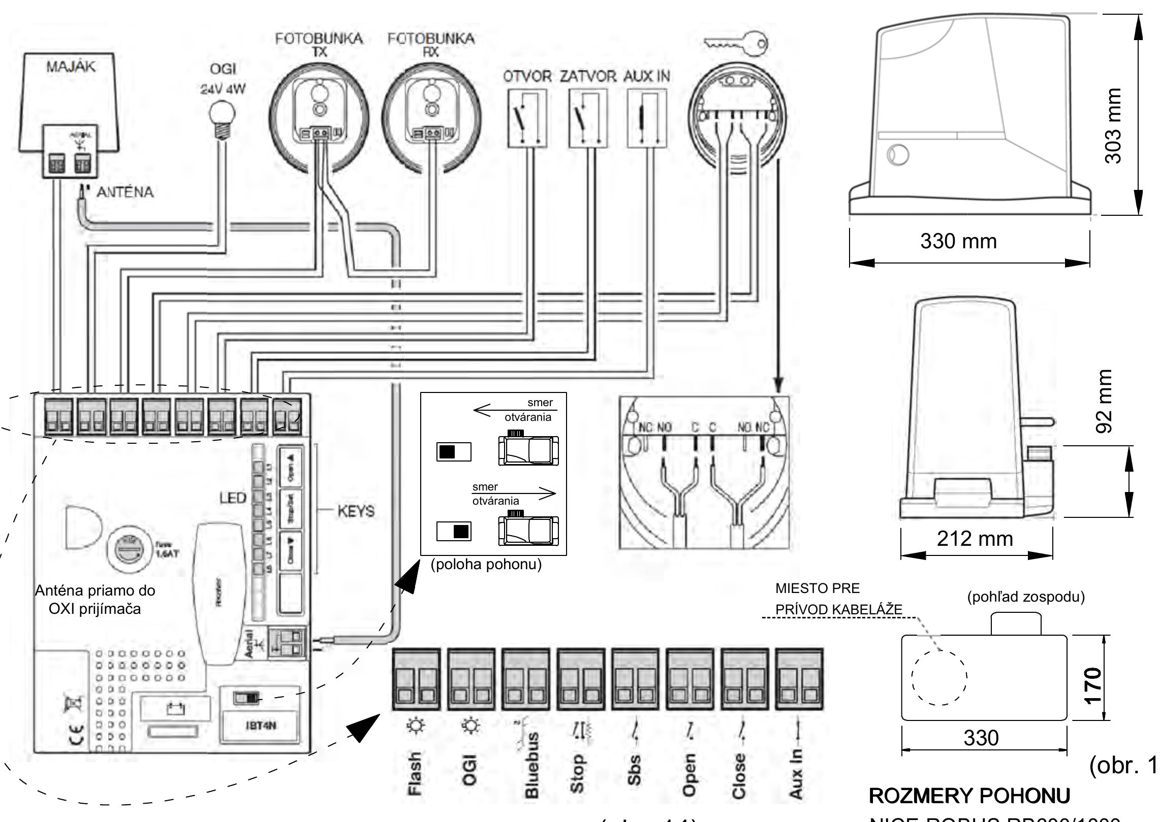
The following excerpt applies exclusively to the older Robus RB generation and the control unit shown in the image. It includes connections for the warning light, photocells and command inputs, as well as the older drive dimensions. Do not use it for Robus RBS.
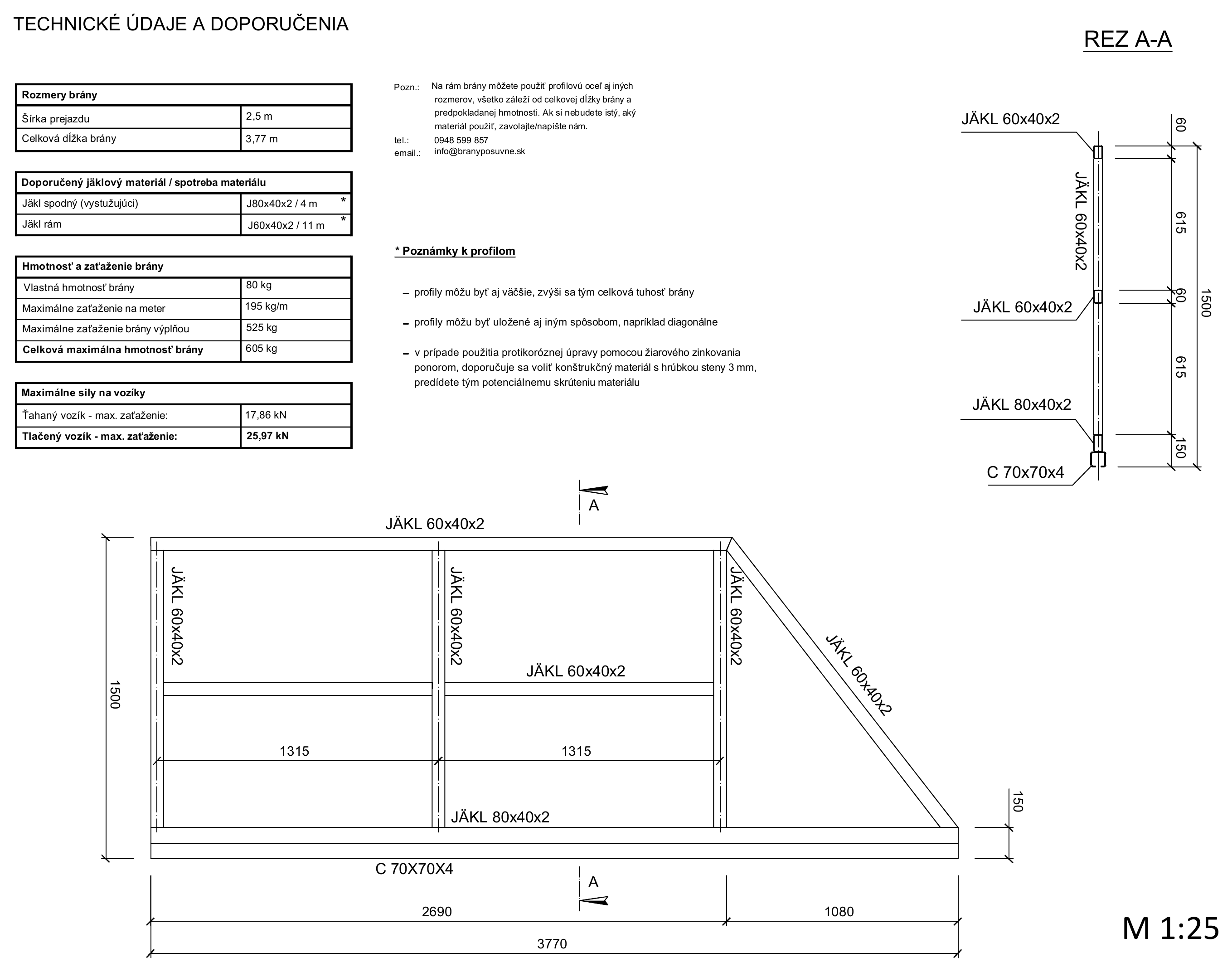
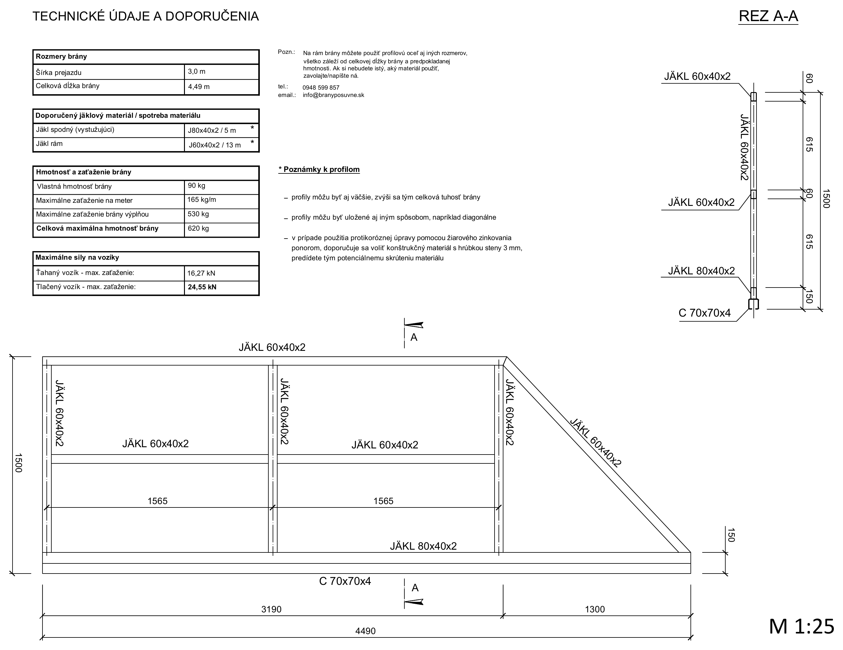
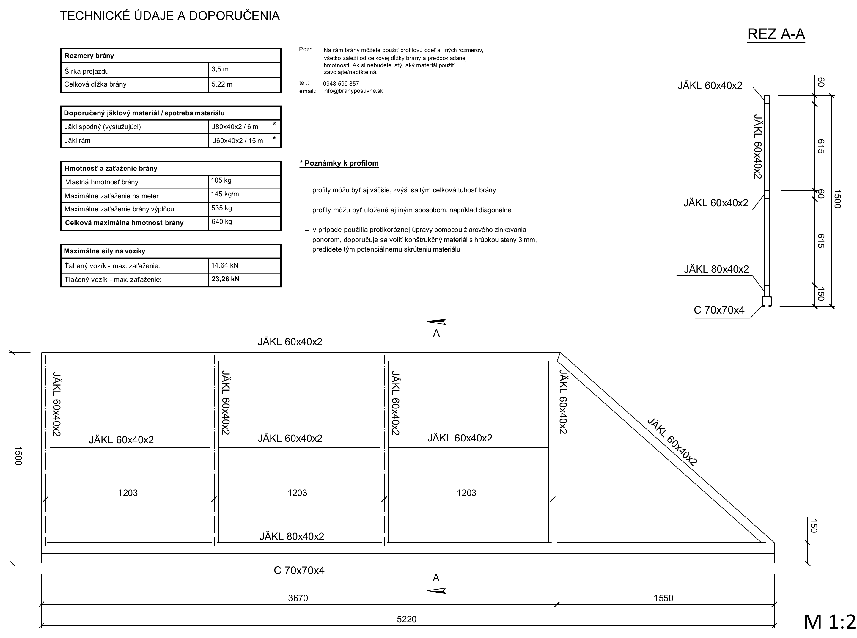
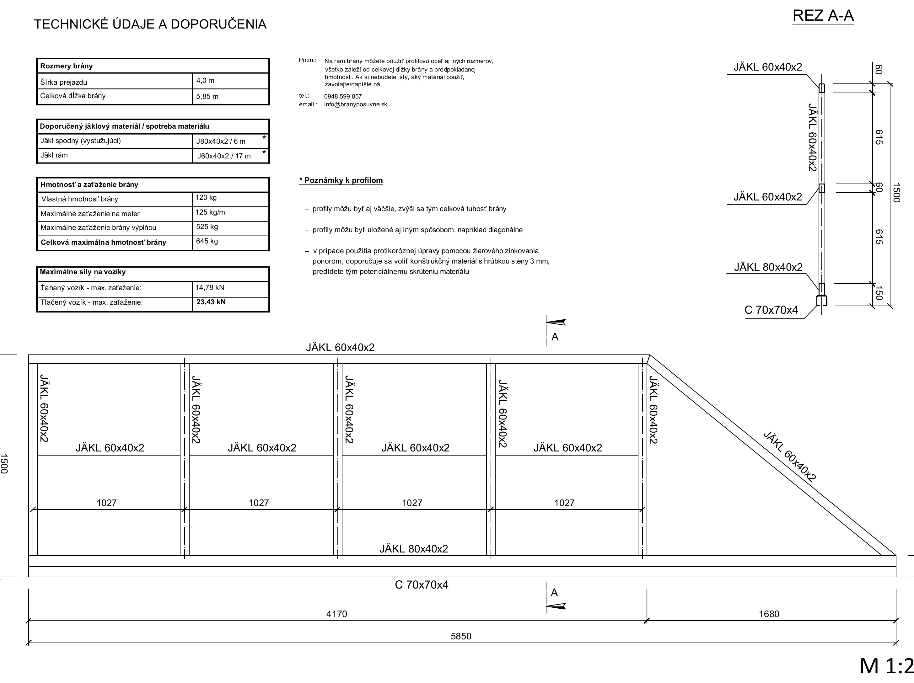
The values in the table apply to specific variants shown in the source drawings listed in the following section.
| Clear opening width | Overall gate length | Gate weight | Max. load per metre | Max. infill weight |
|---|---|---|---|---|
| 2.5 m | 3.77 m | 80 kg | 195 kg/m | 525 kg |
| 3.0 m | 4.49 m | 90 kg | 165 kg/m | 530 kg |
| 3.5 m | 5.22 m | 105 kg | 145 kg/m | 535 kg |
| 4.0 m | 5.85 m | 120 kg | 125 kg/m | 525 kg |
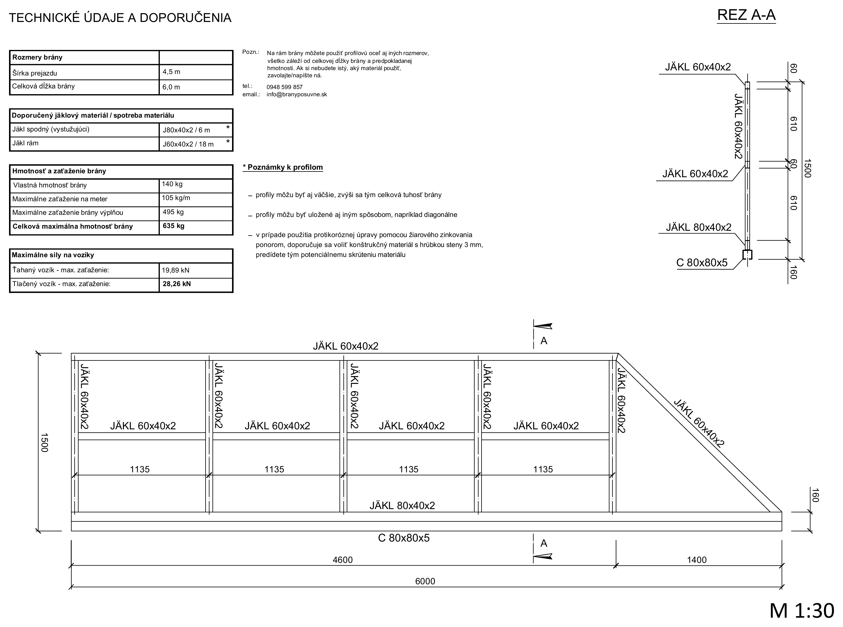
| 4.5 m – short | 6.00 m | 140 kg | 105 kg/m | 495 kg |
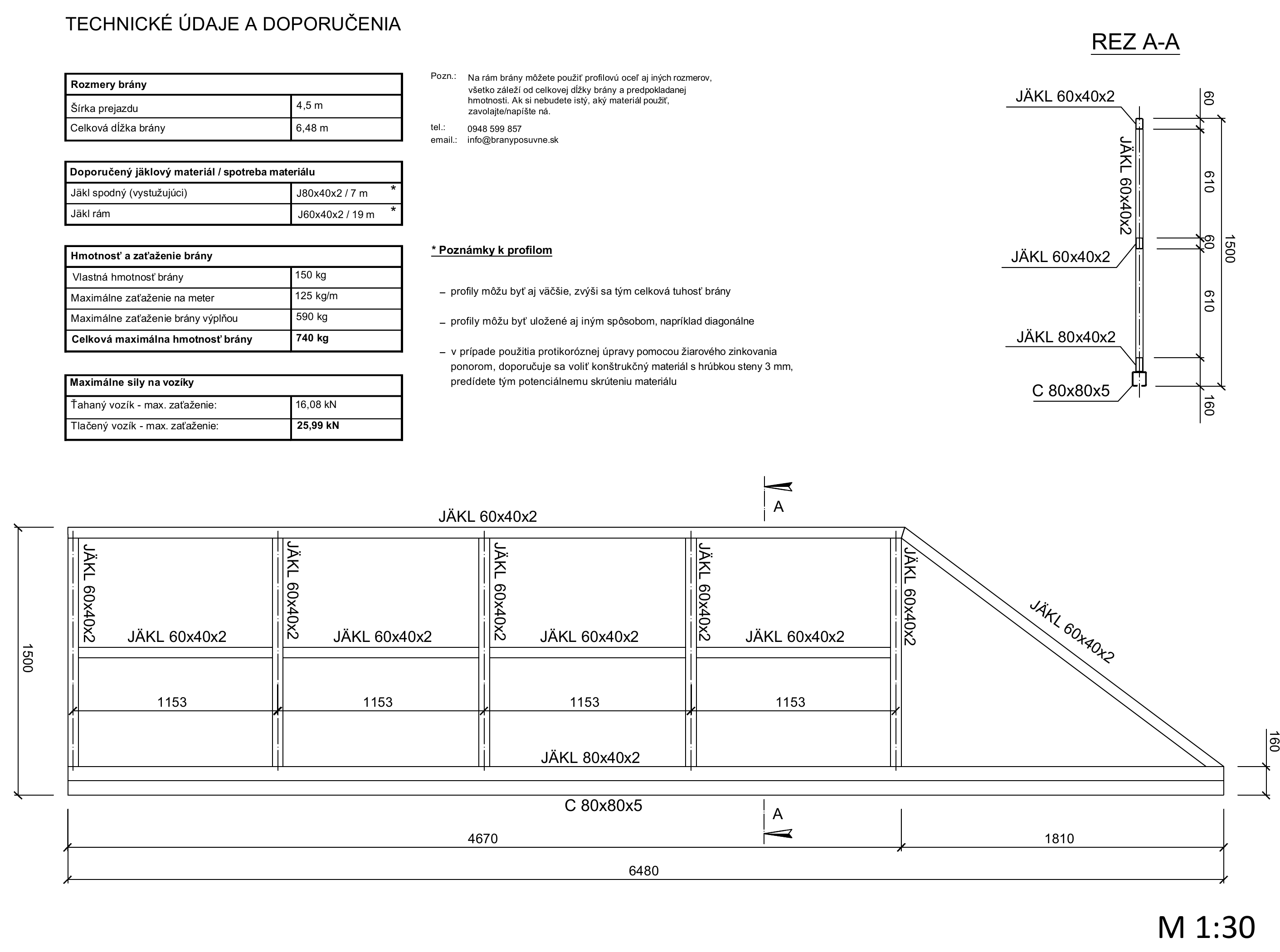
| 4.5 m – full | 6.48 m | 150 kg | 125 kg/m | 590 kg |
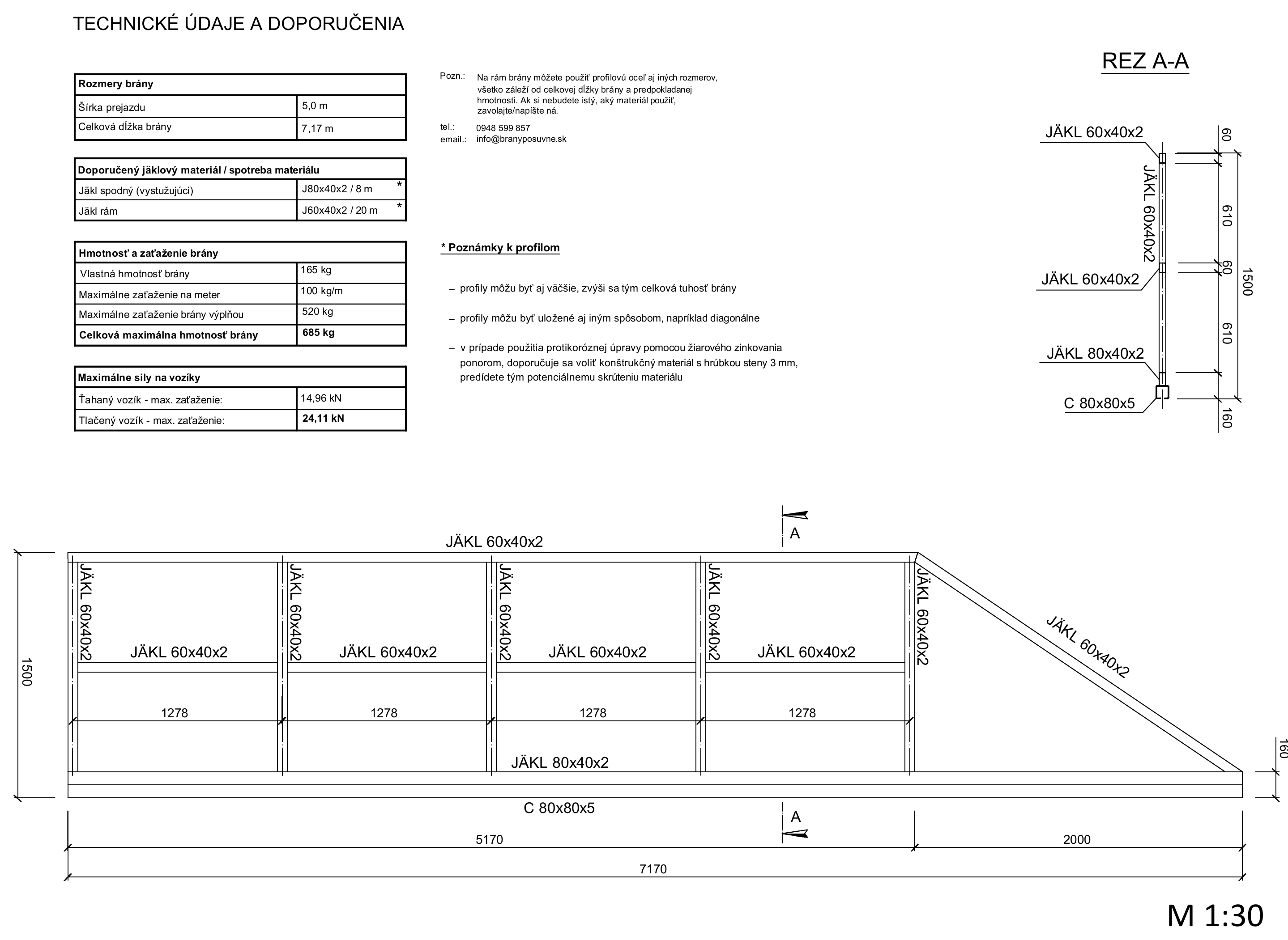
| 5.0 m | 7.17 m | 165 kg | 100 kg/m | 520 kg |
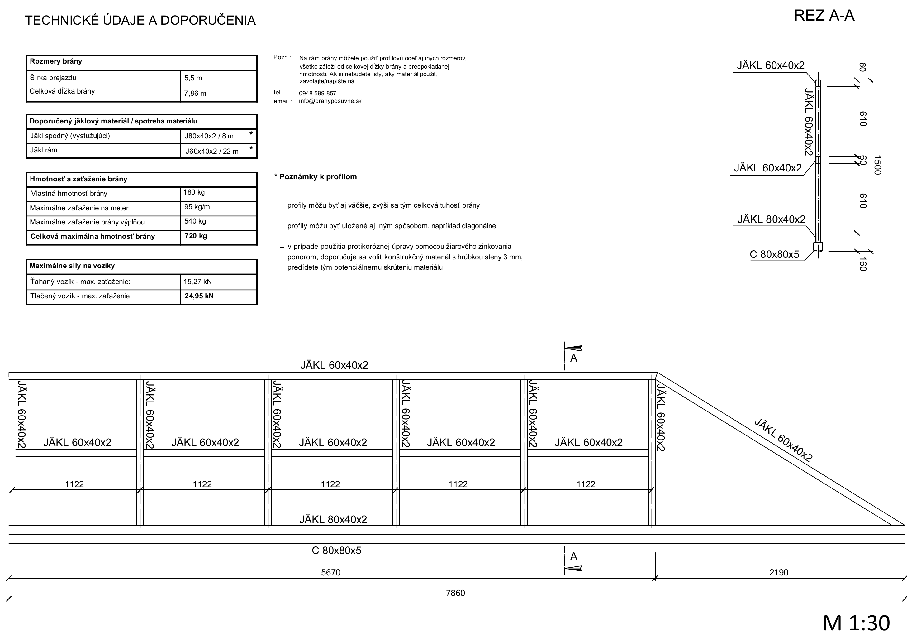
| 5.5 m | 7.86 m | 180 kg | 95 kg/m | 540 kg |
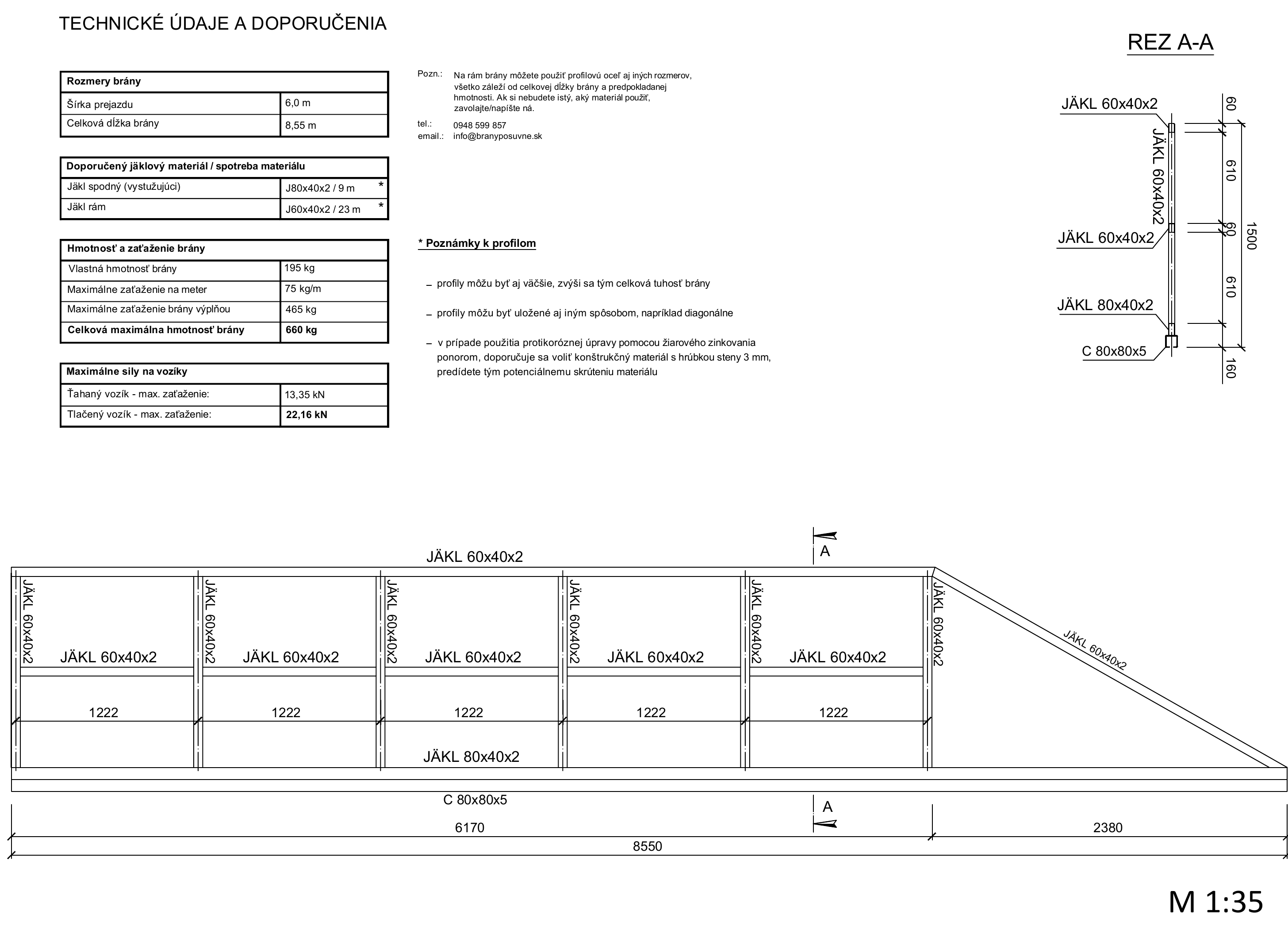
| 6.0 m | 8.55 m | 195 kg | 75 kg/m | 465 kg |
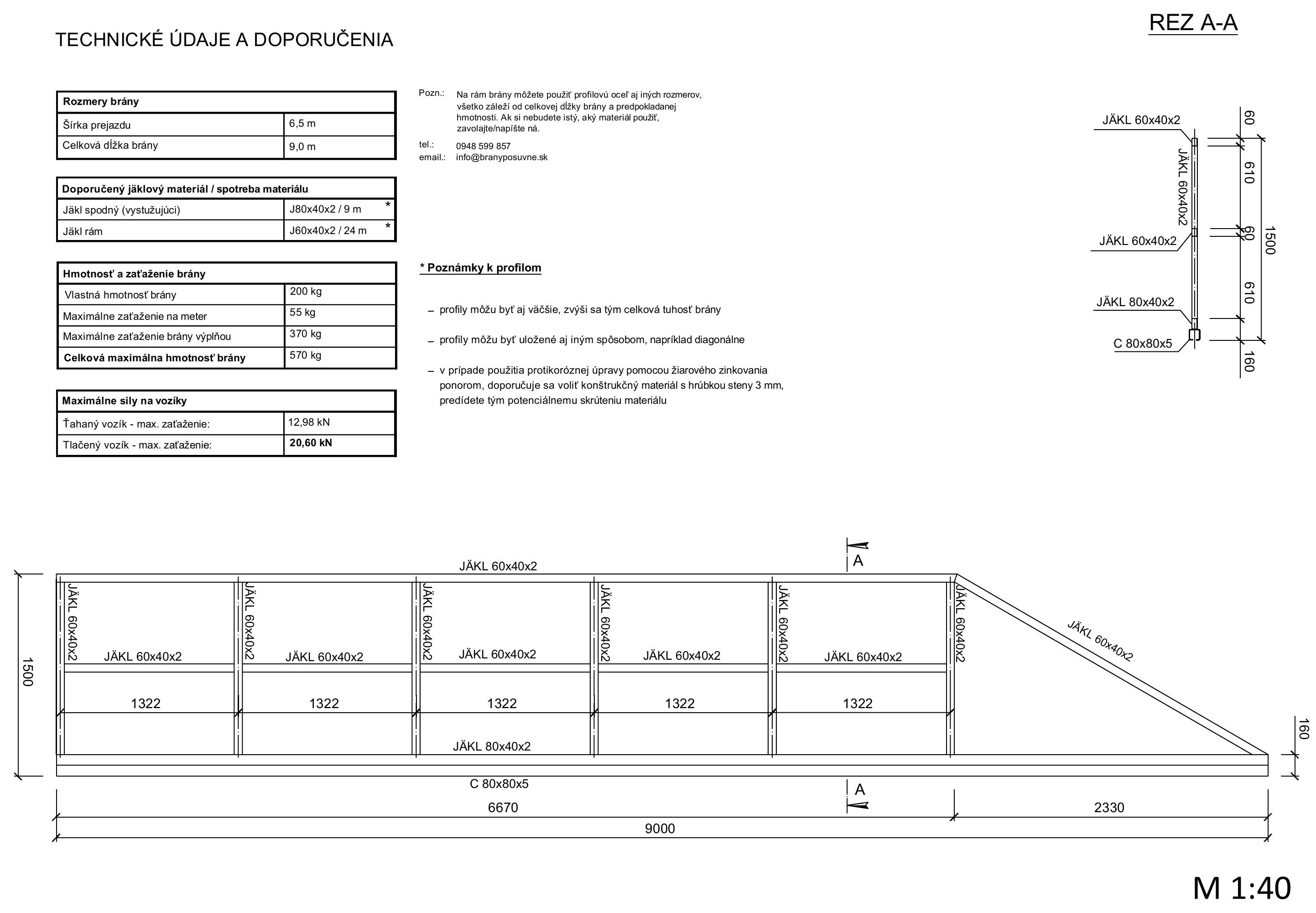
| 6.5 m | 9.00 m | 200 kg | 55 kg/m | 370 kg |
The summary table above also lists the key values as text. The drawings below are intended to show the frame layout, cut locations and dimensions. Click each preview to view the full-resolution image.
2.5 m opening
Overall length 3 770 mm, frame 2 690 mm, counterweight 1 080 mm, frame height 1 500 mm, C-profile 70 × 70 × 4 mm.
3.0 m opening
Overall length 4 490 mm, frame 3 190 mm, counterweight 1 300 mm, frame height 1 500 mm, C-profile 70 × 70 × 4 mm.
3.5 m opening
Overall length 5 220 mm, frame 3 670 mm, counterweight 1 550 mm, frame height 1 500 mm, C-profile 70 × 70 × 4 mm.
4.0 m opening
Overall length 5 850 mm, frame 4 170 mm, counterweight 1 680 mm, frame height 1 500 mm, C-profile 70 × 70 × 4 mm.
4.5 m opening – short version
Overall length 6 000 mm, frame 4 600 mm, counterweight 1 400 mm, frame height 1 500 mm, C-profile 80 × 80 × 5 mm.
4.5 m opening – full version
Overall length 6 480 mm, frame 4 670 mm, counterweight 1 810 mm, frame height 1 500 mm, C-profile 80 × 80 × 5 mm.
5.0 m opening
Overall length 7 170 mm, frame 5 170 mm, counterweight 2 000 mm, frame height 1 500 mm, C-profile 80 × 80 × 5 mm.
5.5 m opening
Overall length 7 860 mm, frame 5 670 mm, counterweight 2 190 mm, frame height 1 500 mm, C-profile 80 × 80 × 5 mm.
6.0 m opening
Overall length 8 550 mm, frame 6 170 mm, counterweight 2 380 mm, frame height 1 500 mm, C-profile 80 × 80 × 5 mm.
6.5 m opening
Overall length 9 000 mm, frame 6 670 mm, counterweight 2 330 mm, frame height 1 500 mm, C-profile 80 × 80 × 5 mm.
This guide deliberately omits prices, stock availability and the old product overview from the PDF. For the latest options, use the website's permanent category pages and have the carriages, C-profile, drive and safety devices checked against your gate's weight and dimensions.
Contact us. We can advise you on choosing components for your specific cantilever sliding gate.
Prepared by Ing. Ján Kubíček.
Last updated: 16. 9. 2026.