NICE MOF - Moon Photocells - photocells with conventional wiring, (1 pair)
| Product availability: | Unavailable | We’ll be happy to help you choose a replacement. Feel free to contact us. |
|---|

Description of NICE MOF - Moon Photocells - photocells with conventional wiring, (1 pair)
Notice: NICE Moon MOF photocells are no longer manufactured and are therefore unavailable. As an alternative, you can choose NICE BF, NICE Era Photocell EPS, or NICE Era Photocell EPM..
Replacement covers for photocells are available to buy: NICE-ND-PRB-MOFB
Outdoor safety photocells NICE MOF (Technical specifications) are installed opposite each other across the gate opening, or at any point where there is a risk of the gate hitting an obstacle. They create an infrared beam along the optical axis, which, when interrupted, sends a signal to stop the gate. When the beam is interrupted, they send a signal to stop the gate. They can be used with devices that support a conventional wiring system (i.e. 12–24V power supply and an NC or NO circuit).
They consist of two synchronised components: TX transmitter and RX receiver.
Installing NICE MOF photocells
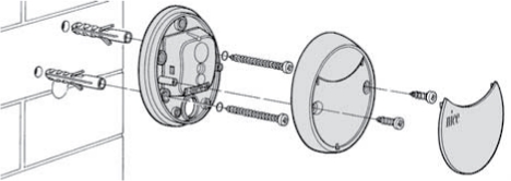
1. Install the photocells on a wall, masonry wall, post, or any suitable surface (surface-mounted) at the same height and facing each other along the same axis. Ensure the mounting surface is level so the photocells can be easily aligned:
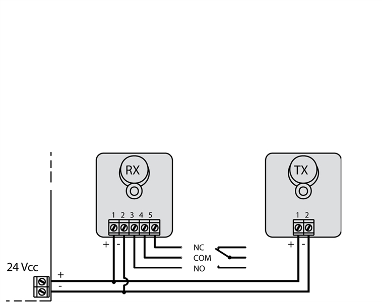
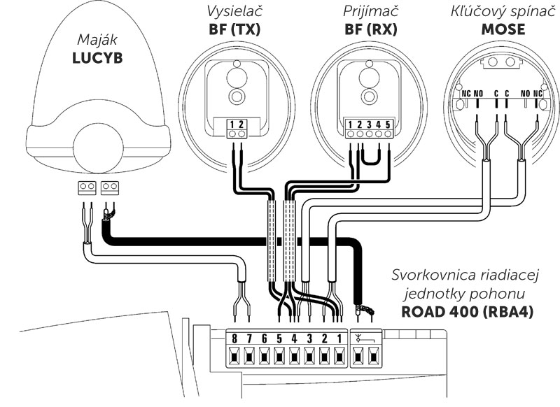
2. Next, wire the photocells according to the diagram supplied with your drive or control unit (see wiring diagram for NICE Road 400 - control unit RBA4). The general wiring diagram is as follows:
3. The photocells are factory-set for a 24V power supply. If you need a 12V supply, bridge the connection with a drop of solder on the back of the circuit board of both the TX transmitter and RX receiver, marked "12V".
4. If the distance between the TX transmitter and RX receiver is greater than 10m, break the connection on the back of the circuit board of the RX receiver, marked "+10m".
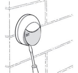
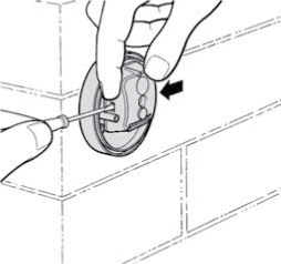
5. If the required opening angle is to be less than ±5°, fit the reducing cone (supplied) to the RX receiver as follows:
| Pop off the photocell cover | Remove the electronics |
|---|---|
 |
 |
| Pop out the circuit board | Fit the reducing cone |
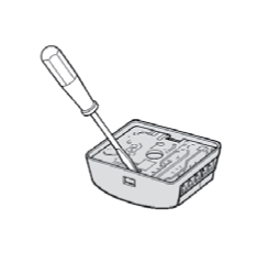 |
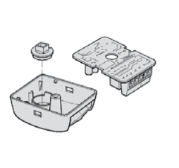 |
6. To test that the wiring is correct, refer to the section Testing operation and troubleshooting, or continue below for information on wiring multiple pairs of photocells:
Wiring two pairs of NICE MOF photocells
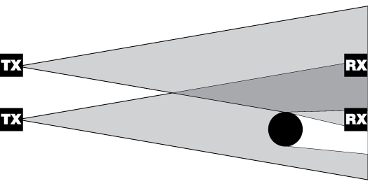
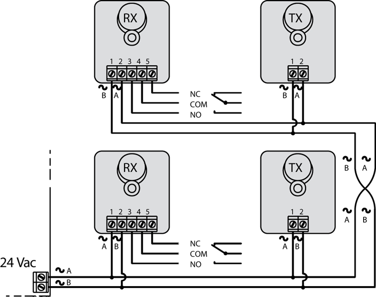
Position the photocells around the gate or garage door. When installing two pairs of photocells, interference may occur between the TX transmitter of the first pair and the RX receiver of the second pair, as shown in the image:
To prevent interference between two pairs installed close to each other, an AC power supply must be available. As shown in the image, break the SYNC connection on both TX transmitters:
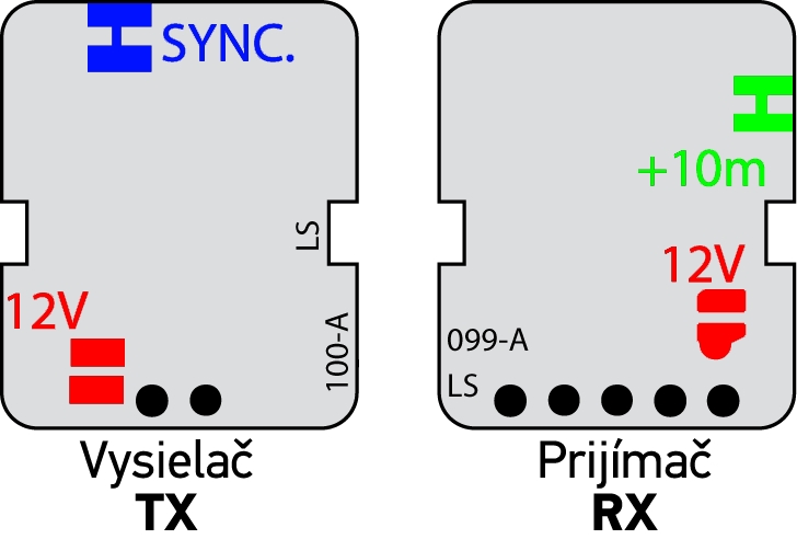
The second pair of photocells must also be wired with reversed polarity, as shown in the image:
Testing operation and troubleshooting NICE MOF photocell wiring
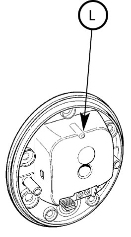 |
After installing the photocells, check the LED behaviour on the RX receiver. The LED flashing patterns indicate the following: |
| LED "L" | Status | What to do |
|---|---|---|
| Off | Everything is OK | Nothing. |
| Flashing slowly | The RX receiver is receiving a weak signal | Adjust the photocell alignment. |
| Flashing rapidly | The RX receiver is not receiving any signal | Check that there is no obstruction on the optical axis between the TX transmitter and RX receiver. Check the alignment of TX and RX. |
| On | Obstacle detected | Remove the obstacle |
NICE MOF photocell specifications
| Product type | Detector for automatic swing gates, sliding gates and garage doors, consisting of a transmitter TX and a receiver RX. |
|---|---|
| Technology | Direct TX-RX optical interpolation with a modulated infrared beam. |
| Power supply/Output |
|
| Current consumption |
One pair: 55mA, consisting of:
|
| Detection capability | Opaque objects larger than 50 mm passing through the optical axis between the TX transmitter and RX receiver at speeds below 1.6 m/s. |
| TX transmitter angle | 20° ±25% |
| RX receiver angle |
|
| Standard range | 15 m (may be reduced by 50% in adverse weather conditions) |
| Maximum range | 30 m with the "+10m" connection broken |
| Relay output | Maximum 500mA and 48V |
| Use in acidic or saline environments, or in environments with an increased risk of explosion | No |
| Installation | Vertical wall mounting |
| Protection rating | IP55 |
| Operating temperature | -20°C to 60°C |
| Dimensions | 69x78x25mm |
| Weight | 50g |
Photocell wiring NICE MOF with the drive NICE Road 400
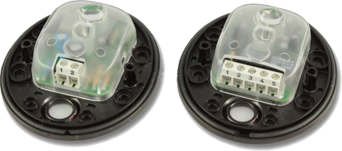
Inside the photocells NICE MOF for gate drives
How can I order this item?
Choose the option that suits you:
- order online: use the buy button to add the goods to your shopping cart (you will find the buy button here in the product variants table).
- order by email: place your order at [email protected]