Manual for a Cantilever Sliding Gate
Technical guide · component selection · suspended gate
From the upper C-profile and trolley units to the bottom guide, stops, lock and sample drawings.
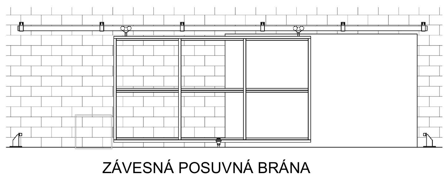
Suspended sliding gate running in an upper C-profile. Click to open the diagram at full resolution.
DIY suspended sliding gate
Ideally, plan the gate in this order. First choose how to mount the upper C-profile, then select the C-profile size, followed by the right trolley units. Only then consider the bottom guide and other accessories such as stops, locks, handles, pull handles or locking hardware.
Manual contents
- Basic components
- Choosing the C-profile mounting method
- Choosing a C-profile for suspended gates
- Choosing trolley units for a suspended gate
- Alternative CAIS system for heavier suspended gates
- Choosing a guide for a suspended gate
- Choosing optional accessories – locks, handles and pull handles
- Drawings
What is a suspended sliding gate?
A suspended sliding gate runs on trolley units housed in the upper load-bearing C-profile. Unlike a track gate, it has no load-bearing track across the opening. The bottom guide only stabilizes the gate against lateral movement.
The load-bearing part of the system is at the top. The C-profile transfers the weight of the gate leaf to the ceiling, beam or wall. The trolley units run inside the profile and support the gate leaf itself. Only guide components and stops are used at the bottom.
Basic components of a suspended gate
| Load-bearing components | C-profile anchored to the ceiling, beam or wall; suspension trolley units; C-profile brackets. |
|---|---|
| Guiding components | Guide rollers to prevent lateral movement and stops to define the end positions. |
| Optional accessories | Hook locks, handles and pull handles for security and convenient operation. |
Choosing the C-profile mounting method
You can mount the C-profile from above to the ceiling or a beam, or from the side to a wall or steel post. Depending on the mounting surface, the brackets can be screwed in place, installed using mechanical or chemical anchors, or welded to a prepared steel structure.
The C-profile can also be drilled directly and screwed to the supporting structure. There is enough space inside the profile for a suitably selected and correctly installed screw not to obstruct the suspension trolley unit. This is an alternative where you do not want or need to weld the profile. However, the type and spacing of the screws, as well as the load-bearing capacity of the mounting surface, must be suited to the gate's weight and usage.
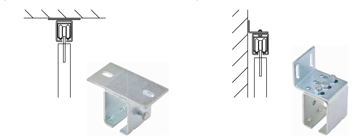
On the left, a bracket for a horizontal surface or beam; on the right, a bracket for a vertical surface or post.
Typical bracket spacing: approximately 80 to 100 cm. Always adjust the actual spacing to the gate's weight, C-profile length, anchoring method and the load-bearing capacity of the structure.
Galvanized brackets
For a standard steel structure, choose a bracket to match the size of the C-profile used:
-
Top bracket for suspended gate C-profile 34 × 31 × 2.0
-
Side bracket for suspended gate C-profile 34 × 31 × 2.0
-
Top bracket for suspended gate C-profile 42 × 52 × 2.5
-
Side bracket for suspended gate C-profile 42 × 52 × 2.5
-
Top bracket for suspended gate C-profile 57 × 67 × 3.0
-
Side bracket for suspended gate C-profile 57 × 67 × 3.0
Stainless steel brackets
If you are using a stainless steel system or installing it in an environment where greater corrosion resistance is required, we also offer top and side INOX brackets for the medium C-profile, 42 × 52 × 2.5 mm.
Choosing a C-profile for suspended gates
The key factors in choosing a profile are the gate's dimensions, weight and intended use. The C-profile must be compatible in size with the trolley units and brackets. With bracket spacing correctly set, the system's load capacity is usually determined by the suspension trolley units rather than the profile itself.
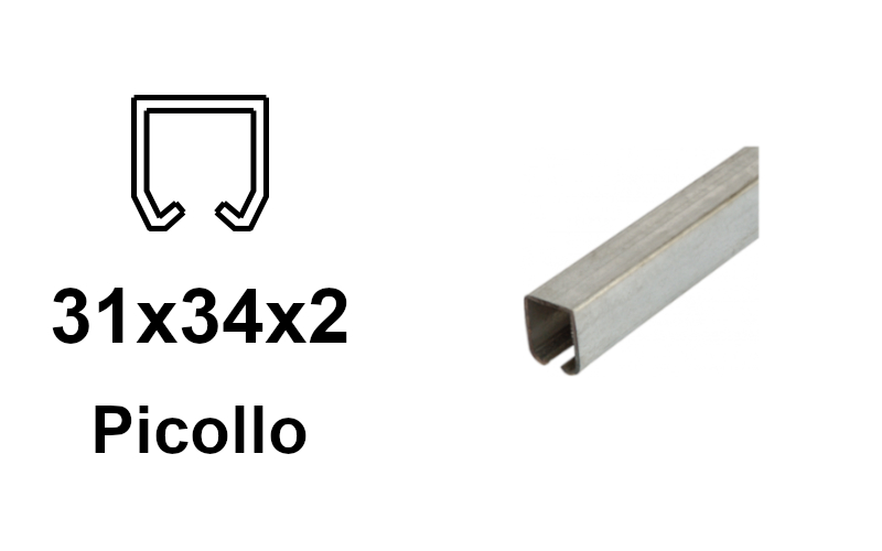
C-profile 34 × 31 × 2 mm
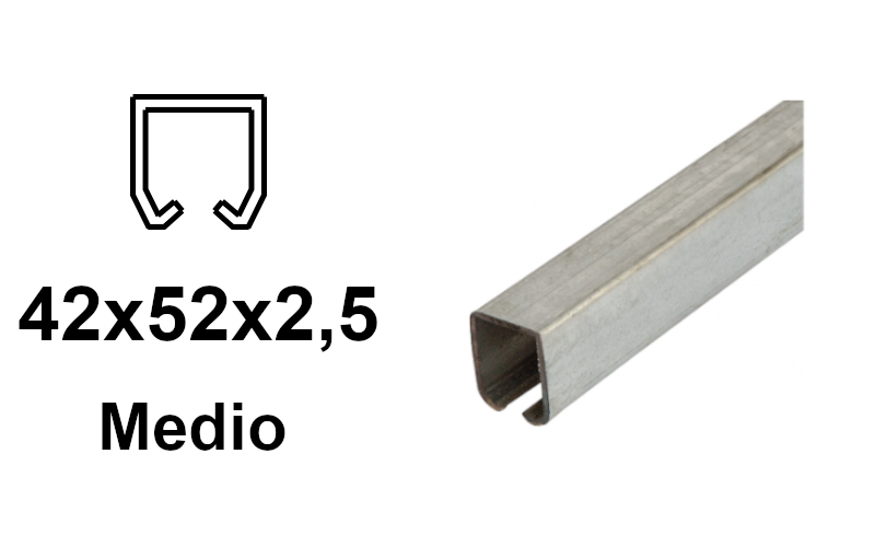
C-profile 42 × 52 × 2.5 mm
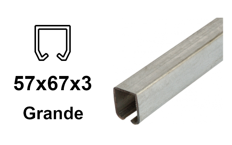
C-profile 57 × 67 × 3 mm
Galvanized C-profiles
Standard sizes for typical suspended gates.
Stainless steel C-profiles
INOX finish for environments with higher corrosion-resistance requirements.
Choosing trolley units for a suspended gate
Always choose a trolley unit to match the specific C-profile size. Also consider the number of rollers, wheel material, how the gate leaf is attached and the required load capacity.
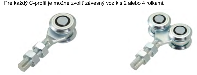
Suspension trolley units with two and four rollers from the original manual.
Steel trolley units with sealed bearings
-
Suspended gate trolley unit, 2 rollers, for 34 × 31 × 2.0 profile
-
Suspended gate trolley unit, 4 rollers, for 34 × 31 × 2.0 profile
-
Suspended gate trolley unit, 2 rollers, for 42 × 52 × 2.5 profile
-
Suspended gate trolley unit, 4 rollers, for 42 × 52 × 2.5 profile
-
Suspended gate trolley unit, 2 rollers, for 57 × 67 × 3.0 profile
-
Suspended gate trolley unit, 4 rollers, for 57 × 67 × 3.0 profile
Nylon trolley units for quieter operation
-
Nylon trolley unit, 2 rollers, for 34 × 31 × 2.0 profile
-
Nylon trolley unit, 4 rollers, for 34 × 31 × 2.0 profile
-
Trolley unit with 4 nylon wheels for 42 × 52 × 2.5 profile
-
Nylon trolley unit, 4 rollers, for 57 × 67 × 3.0 profile
Stainless steel trolley units
Alternative CAIS system for heavier suspended gates
For a heavier gate leaf, you can choose the CAIS system. This system uses a different combination of components from the basic profiles and trolley units listed above. The C-profile, trolley unit and gate-leaf bracket must be compatible with one another – choosing a heavier-duty profile alone is not enough.
Which components go together
| CAIS C-profile | Suspension trolley unit | Gate-leaf mounting bracket |
|---|---|---|
| 73 × 61 × 3.5 mm, Fe or Zn | SPEED C | GD180, M16 thread |
| 95 × 86 × 5 mm, Fe or Zn | SPEED CM | GD200, M20 thread |
For the SPEED C trolley, another option for attaching the gate leaf is the AD150 bracket for a suitable U-profile. Its use and dimensions are listed below in this chapter.
CAIS C-profiles
Choose from two sizes, each available in untreated steel (Fe) or galvanized steel (Zn). All four profiles have holes for bolted mounting. The anchoring method and bracket spacing must be designed according to the actual gate load.
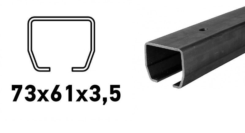
CAIS C-profile 73 × 61 × 3.5 mm, Fe
STAGE SB · untreated steelFor SPEED C trolley.
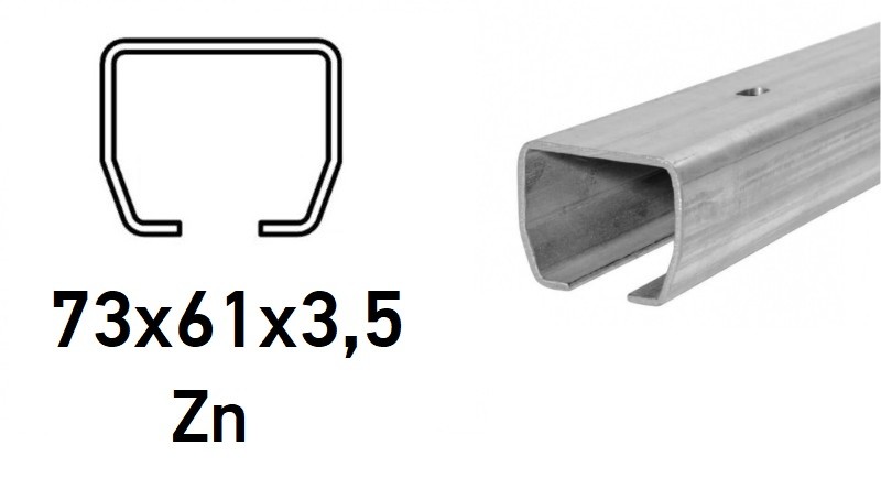
CAIS C-profile 73 × 61 × 3.5 mm, Zn
STAGE SZ · galvanized steelFor SPEED C trolley.
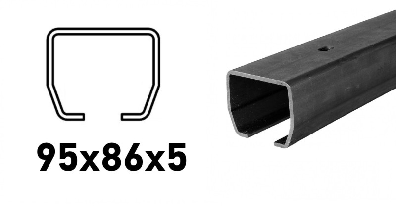
CAIS C-profile 95 × 86 × 5 mm, Fe
STAGE MB · untreated steelFor SPEED CM trolley.
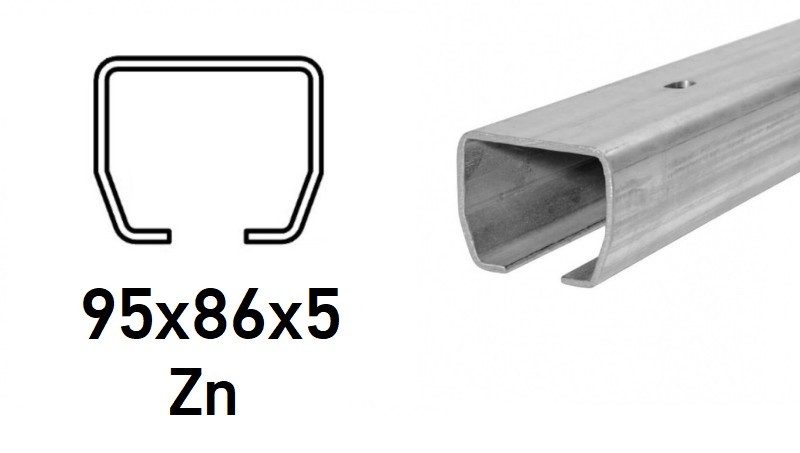
CAIS C-profile 95 × 86 × 5 mm, Zn
STAGE MZ · galvanized steelFor SPEED CM trolley.
CAIS trolleys
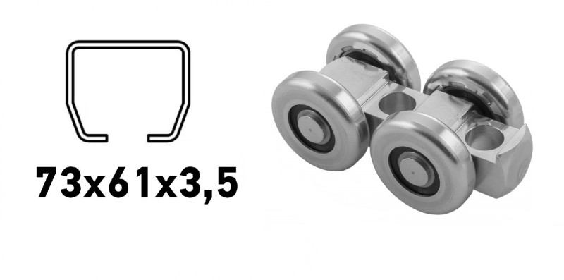
CAIS SPEED C – trolley for 73 × 61 × 3.5 mm C-profile
Four metal rollers, galvanized steel body and Ø 16 mm central hole. For 73 × 61 × 3.5 mm profiles in both Fe and Zn finishes.
Load capacity of one trolley according to the product page: 480 kg . The GD180 bracket (M16), or the AD150 bracket with a suitable U-profile, connects the trolley to the gate leaf.
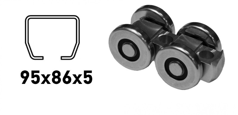
CAIS SPEED CM – trolley for 95 × 86 × 5 mm C-profile
Four metal rollers, galvanized steel body and Ø 20 mm central hole. For 95 × 86 × 5 mm profiles in both Fe and Zn finishes.
Load capacity of one trolley according to the product page: 980 kg . The GD200 bracket (M20) connects the trolley to the gate leaf.
The trolley's load capacity is not the load capacity of the entire gate. The assembly must also be assessed based on trolley placement, gate-leaf attachment, C-profile anchor spacing, and the load-bearing capacity of the supporting structure. The basic trolley table in the following chapter does not apply to CAIS trolleys.
CAIS mounting brackets and attachments
The following parts connect the gate leaf to the suspension trolley. They are not brackets for attaching the upper C-profile to a wall or ceiling.
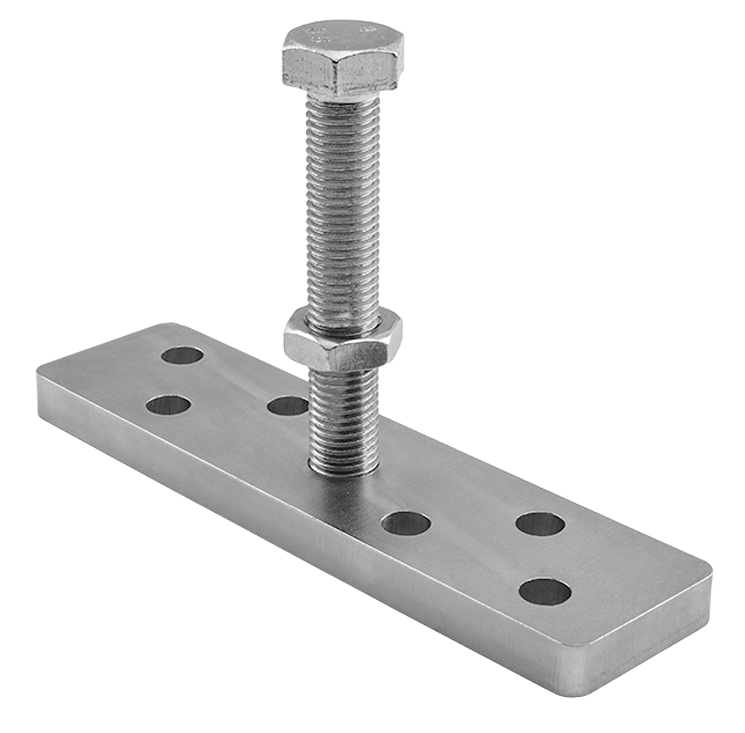
CAIS GD180 – upper adjustable M16 bracket
For the SPEED C trolley and 73 × 61 × 3.5 mm . The galvanized steel bracket connects the trolley to the gate leaf.
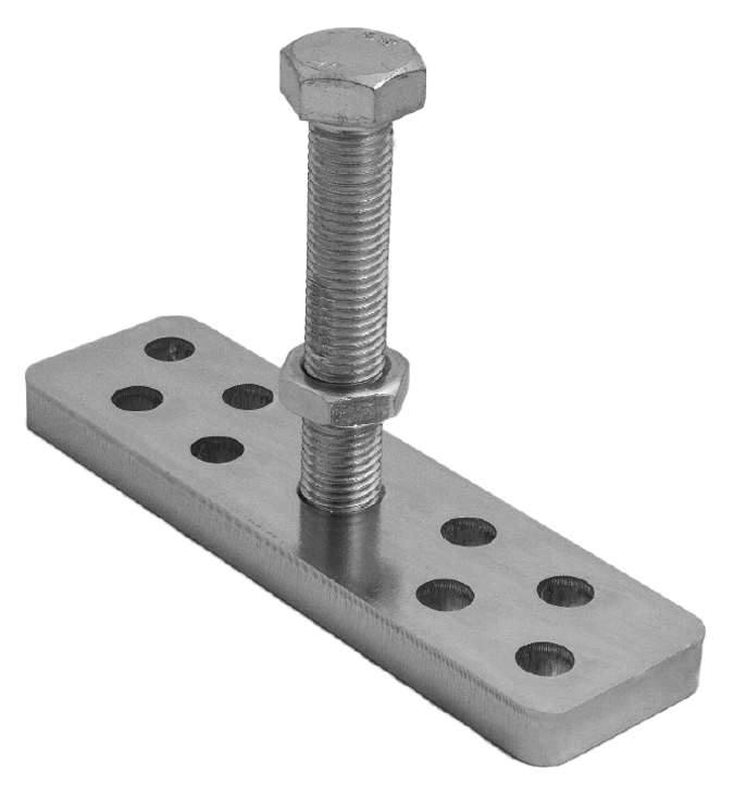
CAIS GD200 – upper adjustable M20 bracket
For the SPEED CM trolley and 95 × 86 × 5 mm . The galvanized steel bracket connects the trolley to the gate leaf.
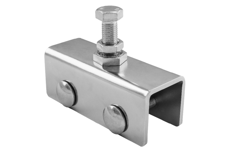
CAIS AD150 – mounting attachment for a gate leaf made from U-profile
Another way to connect the gate leaf to the trolley SPEED C . According to the product page, it is designed for 46 × 60 mm U-profile or 40 × 45 × 40 × 2 mm U-profile in the gate-leaf structure.
Dimensions according to the product drawing: attachment length 150 mm , external width 57 mm , U-section height 58 mm , side plate thickness 5 mm and bolt M16 × 100 . The top plate is 8 mm thick .
For SPEED CM with a Ø 20 mm hole, we do not list it as an interchangeable part; the GD200 bracket is designed for this trolley.
Suspension trolley load capacities
The load capacities in the table are for one trolley, according to the source manual.
If you need a higher load capacity, you can use more trolleys. In practice, they are often arranged in pairs: two trolleys side by side, then a gap, followed by another two trolleys, much like the axles of a car. The exact layout must be adapted to the gate structure and load distribution.
| C-profile | 2 rollers | 4 rollers |
|---|---|---|
| 34 × 31 × 2 mm | 30 kg | 50 kg |
| 42 × 52 × 2.5 mm | 100 kg | 250 kg |
| 57 × 67 × 3 mm | 175 kg | 350 kg |
Important: the table reproduces the values from the source manual. For each specific trolley, always check the load capacity stated on the product page, especially if it has a different type of rollers.
Load distribution between trolleys
Using more trolleys does not necessarily reduce the maximum load on each trolley. Their positioning and structural deflection are decisive.
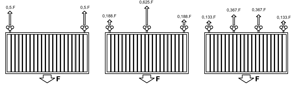
Diagram showing the distribution of total load F across two, three and four trolleys.
| Number of trolleys | Load distribution from left to right |
|---|---|
| 2 | 0.5 F + 0.5 F |
| 3 | 0.188 F + 0.625 F + 0.188 F |
| 4 | 0.133 F + 0.367 F + 0.367 F + 0.133 F |
With three trolleys, the middle trolley may carry 0.625 F, which is more than the 0.5 F carried by each of a correctly spaced pair of trolleys.
Practical note: If you want to use more trolleys, they are typically not spaced evenly along the entire length of the gate leaf. In practice, two trolleys are placed close together, with another pair close together, much like the axles on a car. The exact solution depends on the gate design and how the load is distributed.
Choosing a guide system for a suspended gate
The bottom guide prevents the suspended gate from swinging sideways and helps ensure smooth, stable movement. First, review the guide options, then choose a solution to suit the frame, available space and installation method.
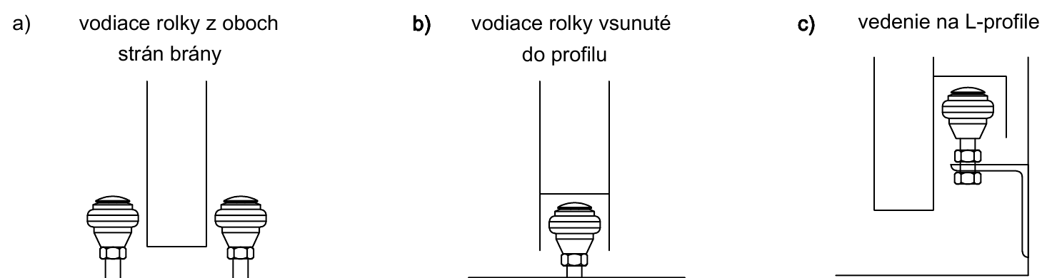
Guide rollers on both sides, a roller fitted inside the profile, and an L-profile guide.
Browse the category for an overview of available rollers and other solutions: bottom guides for suspended gates .
For a heavier gate: A track for a track-based sliding gate can be installed at the bottom, along with bottom wheels. This distributes the weight between the top and bottom guides, so the entire gate leaf is not supported solely by the top C-profile and suspension trolleys. This type of combined solution should be designed to suit the gate weight and supporting structure.
Guide track
Bottom guide track for suspended and folding gates
The 83 × 51 mm galvanized track is installed along the length of the gate. A bottom guide pin with a bearing runs in its groove.
Rollers
All bottom guide options
Choose from bottom guide wheels, adjustable rollers and solutions for different suspended-gate frame widths.
Stops for suspended gates
Mechanical stops define the end positions and prevent the gate from sliding out of the C-profile. A stop can be fitted inside the C-profile or anchored to the ground or a post.
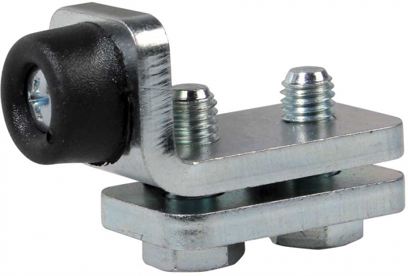
Stop in the top C-profile
Internal stop for a suspended gate C-profile
It is fitted inside the top profile and limits trolley movement at the end position.
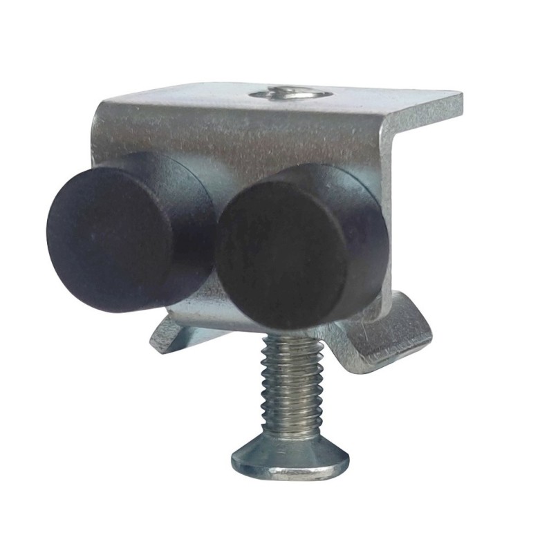
Stop for small profile
Internal stop for C-profile, 34 × 31 × 2.0
Sized for the small 34 × 31 × 2.0 mm suspended-gate C-profile.
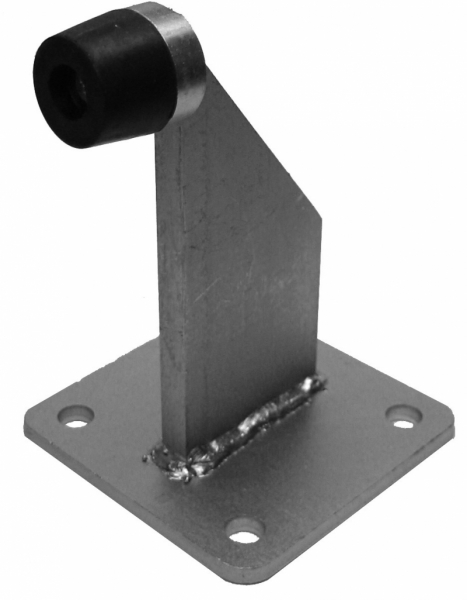
Bottom stop, galvanized
Bottom stop with base plate
It is screwed to a solid surface and sets the position of the bottom of the gate leaf.
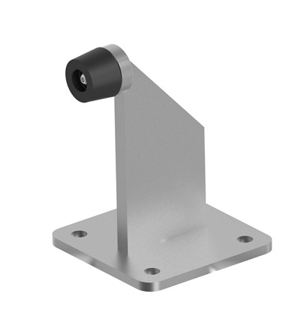
Bottom stop, stainless steel
Stainless steel bottom stop with base plate
Stainless steel version of the screw-on bottom stop.
Choosing optional accessories: locks, handles and pulls
A hook lock is used to secure a manually operated sliding gate. Choose the size to suit the frame profile and the required operating method. Then pair the lock with a suitable handle or pull handle.
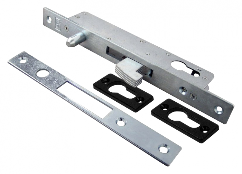
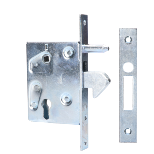
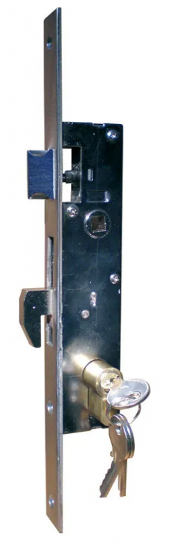
Stainless steel lock
Stainless steel hook lock ZH-09 INOX
Stainless steel version with a cylinder for sliding and swing gates.
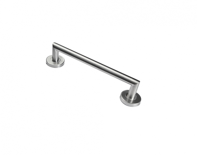
Gate pull handle
Stainless steel square pull handle, 268 × 64 mm
Pull handle for convenient manual operation of a suspended gate.
All hook locks · Lever handles, knobs and escutcheons · Gate pull handles
Frequently asked questions and answers
1. Does a suspended gate need a running track?
In a standard suspended-gate setup, the top C-profile and trolleys carry the weight; the bottom of the gate leaf only stabilizes it. For a heavier gate, however, a combined solution with bottom wheels and a track for a track-based sliding gate , which distributes the load between the top and bottom, can be designed.
2. How far apart should the C-profile brackets be installed?
The manual gives approximately 80 to 100 cm as the most common spacing. The actual spacing must take into account the weight of the gate leaf, profile length, anchoring method and load capacity of the supporting structure.
3. How do I choose the right C-profile?
Based on the gate dimensions and total weight, including the infill. The suspension trolley must be designed for the same C-profile size, and its load capacity must be suitable for the actual load.
4. Is the weight distributed evenly when using three or four trolleys?
Not always. According to the diagram in the manual, with three trolleys the middle trolley may carry up to 0.625 of the total load F. When using four trolleys, they are often installed in two pairs close together, much like the axles on a car, rather than evenly along the entire length of the gate leaf. The exact positioning depends on the gate design and how the load is distributed.
5. Which type of bottom guide is best?
It depends on the frame and the space around the gate. You can use rollers on both sides of the frame, a roller running inside the bottom profile, a bottom guide track or an L-profile guide. The guide should stabilize the gate leaf without creating unnecessary friction.
6. What are end stops used for?
They define the open and closed positions and prevent the trolleys from sliding out of the C-profile. A stop can be fitted in the C-profile or anchored to the ground or a post.
Suspended gate design examples
The drawings have been rotated to the natural orientation. The preview is sized to fit the center column; click to open the full-resolution drawing with all dimensions.
Suspended gate with a clear opening of 1.5 × 2.5 m
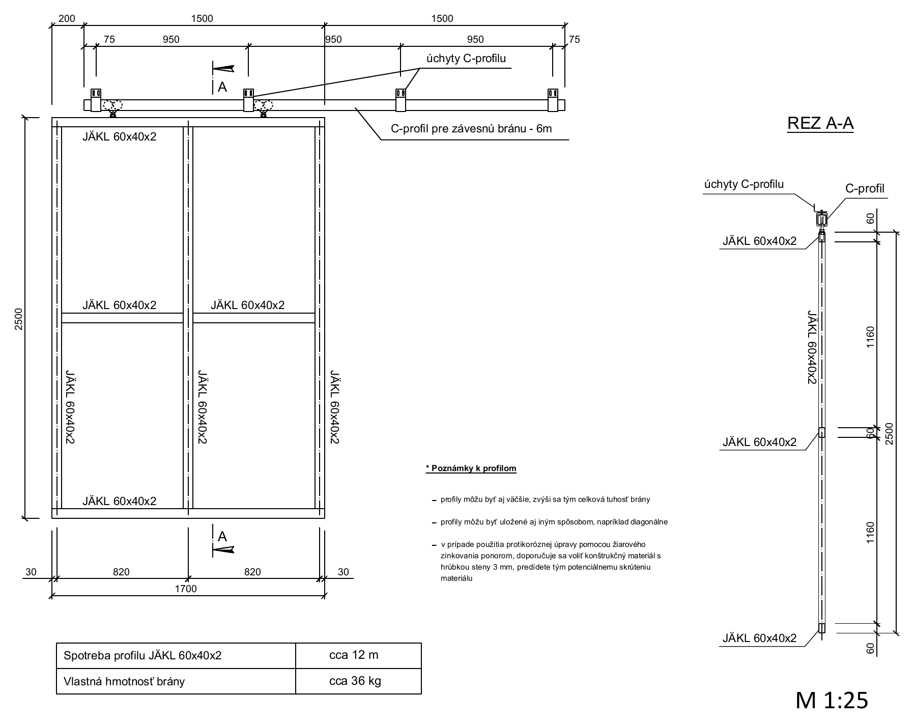
- Frame 1 700 × 2 500 mm
- Profile JÄKL 60 × 40 × 2 mm
- Profile required approx. 12 m
- Net weight approx. 36 kg
Suspended gate with a clear opening of 3.0 × 2.5 m
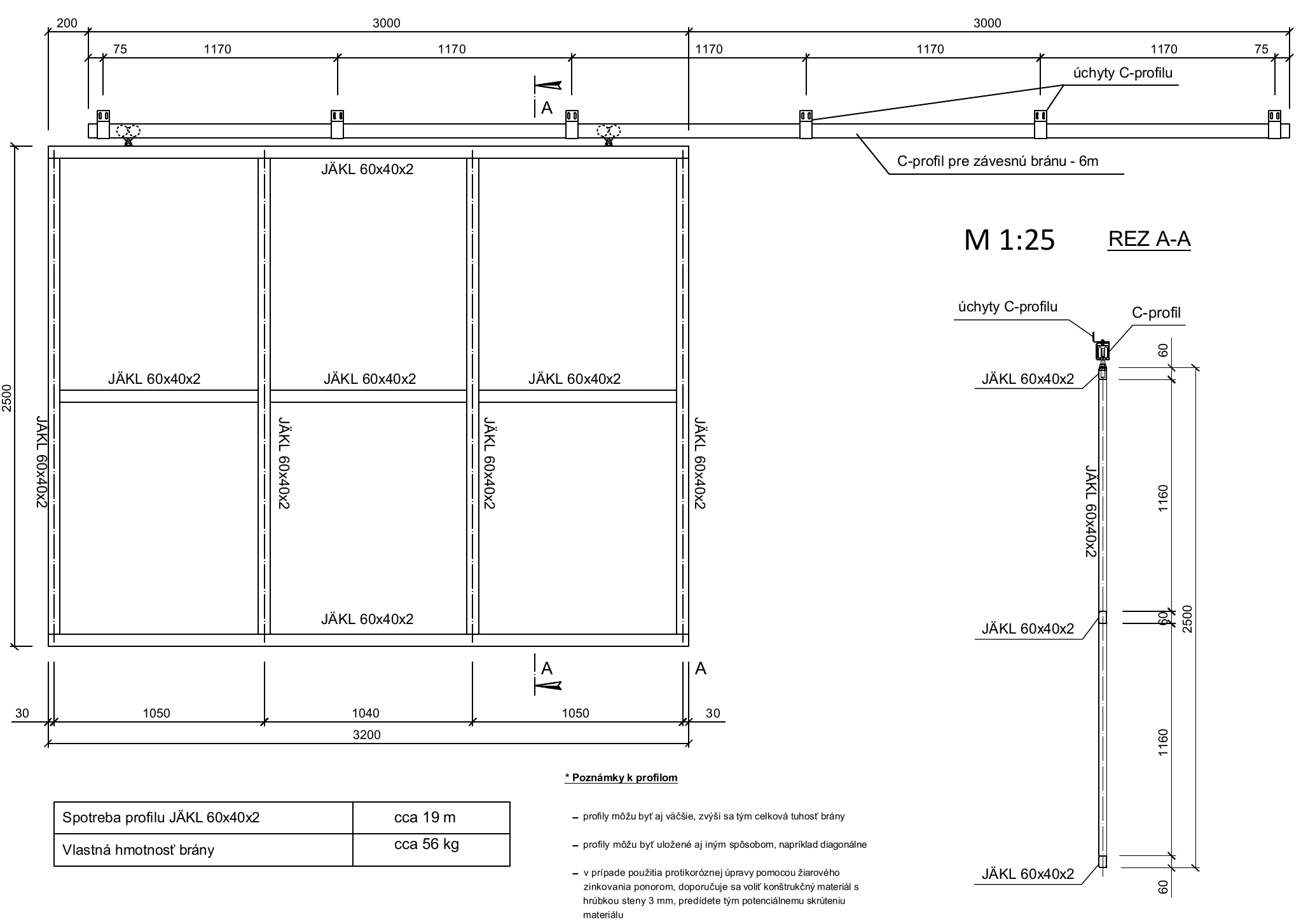
- Frame 3 200 × 2 500 mm
- Profile JÄKL 60 × 40 × 2 mm
- Profile consumption approx. 19 m
- Weight approx. 56 kg
Cantilever gate for a clear opening of 4.5 × 2.5 m
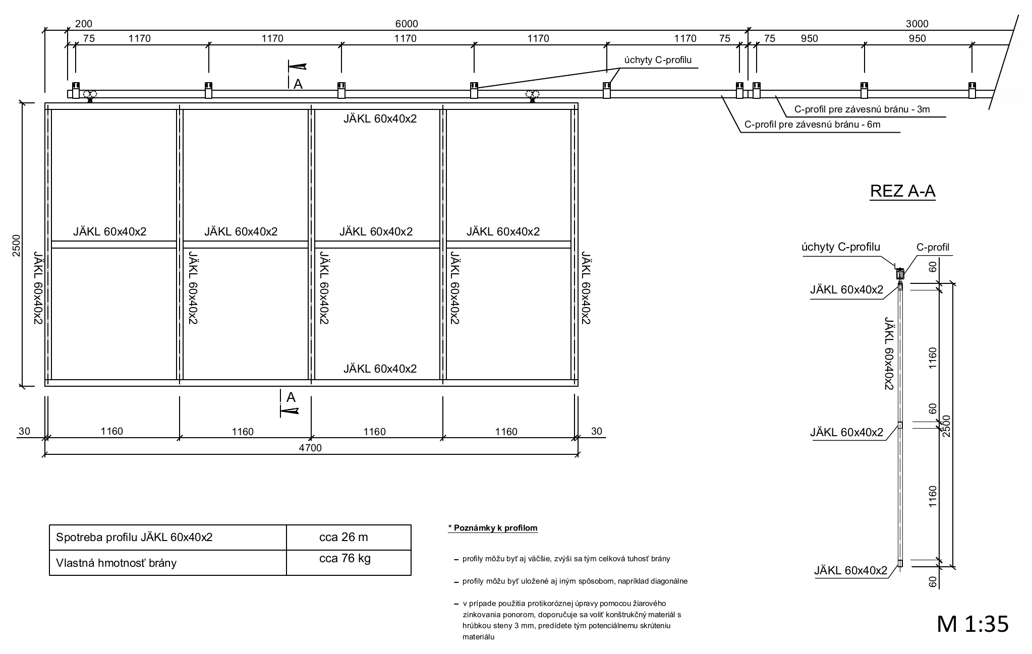
- Frame 4 700 × 2 500 mm
- Profile JÄKL 60 × 40 × 2 mm
- Profile consumption approx. 26 m
- Weight approx. 76 kg
Cantilever gate for a clear opening of 6.0 × 2.5 m
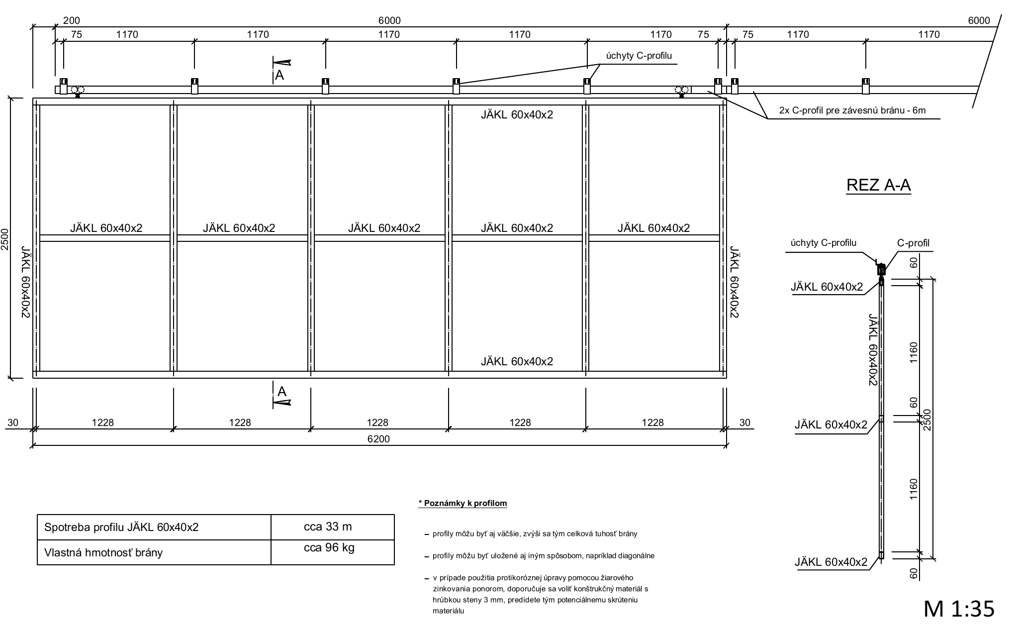
- Frame 6 200 × 2 500 mm
- Profile JÄKL 60 × 40 × 2 mm
- Profile consumption approx. 33 m
- Weight approx. 96 kg
Note on profiles: Profiles can be larger or arranged differently, for example diagonally. For hot-dip galvanizing, the manual recommends using structural material with a 3 mm wall thickness to reduce the risk of twisting. For a different design, a thinner profile wall may also be used if, following a technical assessment, it is appropriate for the dimensions, weight and rigidity of the specific gate.
The dimensions shown are for illustration only. The cantilever gate can also be designed in other dimensions and welded from different hollow sections. For non-standard dimensions or a heavier infill, we recommend checking the profile, number of carriages and anchoring method for the specific situation.
Ordering and advice
» Ask about the technical solution
If you haven’t found the information you’re looking for, contact us. We can advise you on choosing a C-profile, brackets, carriages, bottom guide and accessories for your cantilever gate.
Information we need to select suitable products for you
- the clear width and height of the opening,
- the dimensions of the entire gate leaf and its estimated weight including infill,
- a photo or sketch of the location where the C-profile will be anchored,
- how you would like to arrange the bottom guide.
Technical note: The examples shown are for guidance only and do not replace an assessment by a qualified professional of the specific supporting structure, anchoring method and installation conditions.
Prepared by Eng. Ján Kubíček.
Last updated: 16. 9. 2026.